Workman GTX Electric Lithium Page 3B -- 61 Electrical System
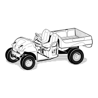
5. Disconnect electrical conductors from SC2: traction
controller and position them away from controller:
A. Remove cap screw, lock washer, flat washer and
cable connector from controller terminals B+, B--,
M1, M2 and M3 (Fig. 64).
B. Carefully unplug wire harness connector from
controller.
C. Position cables and wire harness connector
away from controller.
6. Support traction controller to prevent it from falling.
7. Remove four (4) bolts (13) that secure traction con-
trollertocontrollerbracket.Carefully remove controller
from vehicle.
Installation (Fig. 63)
1. Position SC2: traction controller to controller bracket
and secure with four (4) bolts (13). Torque the bolts (13)
from 90 to 110 in--lb (10 to 12.4 N--m).
2. Make sure controller terminals and cables are clean
(nocorrosion)andingoodcondition.
3. Connect electrical conductors to traction controller:
A. Carefully plug wire harness connector into trac-
tion controller. Make sure that connector is fully
plugged into traction controller socket.
B. Secure controller cables to controller terminals
B+,B--,M1,M2andM3withcapscrew,lockwasher
and flat washer (Fig. 64). Torque cap screws from 90
to 110 in--lb (10 to 12.4 N--m).
4. Connect the conductors between the battery pack
and vehicle components (see Opening Battery Circuit in
the General Information section of this chapter). Make
sure to torque hex nuts on battery terminals from 72 to
88 in--lb (8 to 9 N--m).
5. After all cable connections are made, apply Toro bat-
tery terminal protector (see Special Tools) to all battery
posts and controller cable connectors to prevent corro-
sion. Make sure that cable terminal boots are positioned
over all connections.
6. Secure rear frame panel cover to vehicle. Lower and
secure cargo box. Install seat base assembly.
7. Before returning vehicle to operation, fully charge
the batteries by connecting the on --board battery char-
ger to an appropriate electrical outlet.
Figure 64
1. SC2: T raction controller
2. B+ terminal (+ cable from main contactor)
3. B-- terminal (-- cable from left, rear battery)
4. M1 terminal (cable to motor terminal W)
5. M2 terminal (cable to motor terminal V)
6. M3 terminal (cable to motor terminal U)
7. Fuse (425 A)
43 5
6
1
2
7
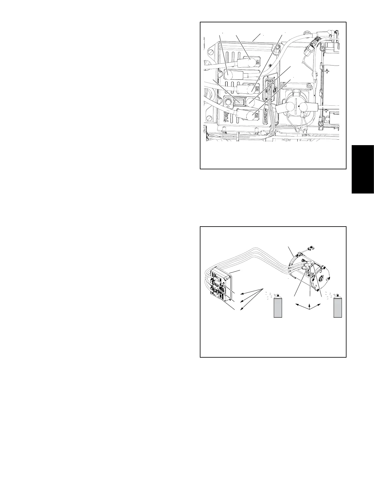
1. SC2: Traction controller
2. M1 terminal
3. M2 terminal
4. M3 terminal
5. Terminal W
6. Terminal V
7. Terminal U
8. Traction motor
Figure 65
567
2
1
8
3
4
90 to 110 in--lb
(10 to 12.4 N--m)
72 to 88 in--lb
(8 to 10 N--m)
Electrical
System

 Loading...