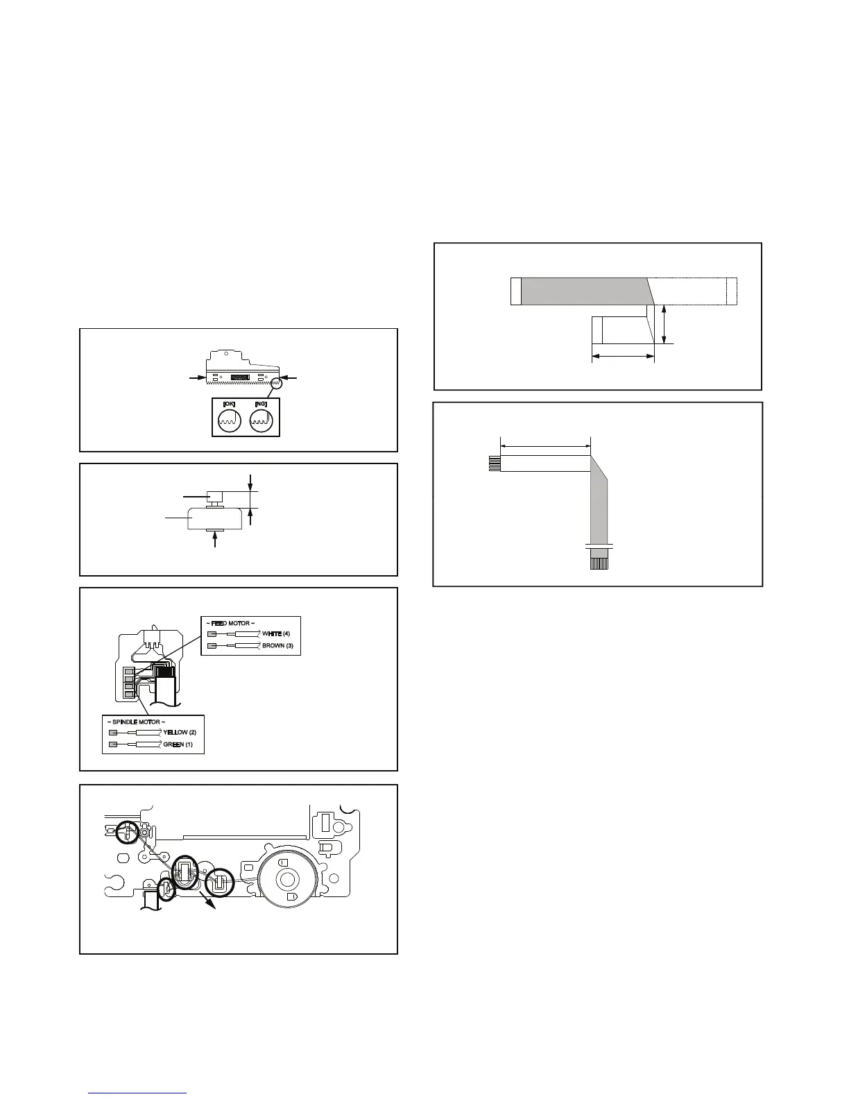
When installing the Rack Feed Ass'y, push both ends to
align the teeth as shown Fig. 2-2-B. Then install it.
In case of the Gear Motor installation, check if the value
of the Fig. 2-2-C is correct.
When installing the wire of the Switch PCB Ass'y, install it
Manual soldering conditions
Soldering temperature: 320 ± 20
Soldering time: Within 3 seconds
Soldering combination: Sn-3.0Ag-0.5Cu
After the assembly of the Traverse Ass'y, hook the wire
on the Traverse Ass'y as shown Fig. 2-2-E.
Rack Feed Ass'y
Push
Push
Fig. 2-2-B
2-3: FFC WIRE HANDLING
1. When installing the FFC, fold it correctly and install it as
shown from Fig. 2-3-A to Fig. 2-3-B.
NOTE
1. Do not make the folding lines except the specified
positions for the FFC.
[ 24 pin FFC ]
Fig. 2-3-A
Printing Surface
Fold it by 90
o
To Pick Up PCB
[ 6 pin FFC ]
Fold
• Install wire from (1) to (4) in order.
• Lossen the wire in the direction of the arrow.
Feed Motor
Safety surface for pressing
of the insert.
Fig. 2-2-C
Switch PCB Ass'y
Fig. 2-2-D
Traverse Ass'y
Check Hook
Check Hook
Check Hook
Check Hook
Fig. 2-2-E
Fig. 2-3-B
 Loading...