DISASSEMBLY INSTRUCTIONS
B2-1
Main Frame Ass'y
Check Hook
2. REMOVAL OF DVD DECK PARTS
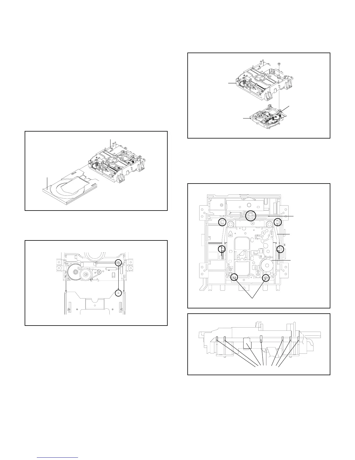
2-1: TRAY (Refer to Fig. 2-1-A)
Set the Tray opened. (Refer to the DISC REMOVAL
METHOD AT NO POWER SUPPLY)
Unlock the 2 supports 1 and remove the Tray.
1.
2.
Fig. 2-1-A
Tray
Main Frame Ass'y
1
NOTE
1.
In case of the Tray installation, install them as the circled
section of Fig. 2-1-B so that the each markers are met.
2-2: MAIN CHASSIS ASS'Y (Refer to Fig. 2-2-A)
Remove the screw 1.
Unlock the 2 supports 2.
Remove the Insulator (R) from the Main Frame Ass'y.
Remove the Main Chassis Ass'y.
1.
2.
3.
4.
Fig. 2-2-A
Tray
Main Frame Ass'y
Fig. 2-1-B
Insulator (R)
NOTE
1. Do not disassemble the DVD DECK PARTS except listed
parts here. Minute adjustments are needed if the
disassemble is done. If the repair is needed except listed
parts, replace the DVD MECHA ASS'Y.
1
1
2
Main Frame Ass'y
Main Chassis Ass'y
2
• Screw Torque: 2.0 ± 0.5kgf•cm
NOTE
1.
2.
In case of the Main Chassis Ass'y, install it from (1) to (4)
in order. (Refer to Fig. 2-2-B)
In case of the Main Chassis Ass'y installation, hook the
wire on the Main Frame Ass'y as shown Fig. 2-2-C.
Fig. 2-2-B
Fig. 2-2-C
(1)
(2)
(3)
(3)
(4)
(3)
Check Lock
(4)
Main Chassis Ass'y
Rack Loading
Main Frame Ass'y (Bottom Side)
Traverse Holder
 Loading...