– 38 –
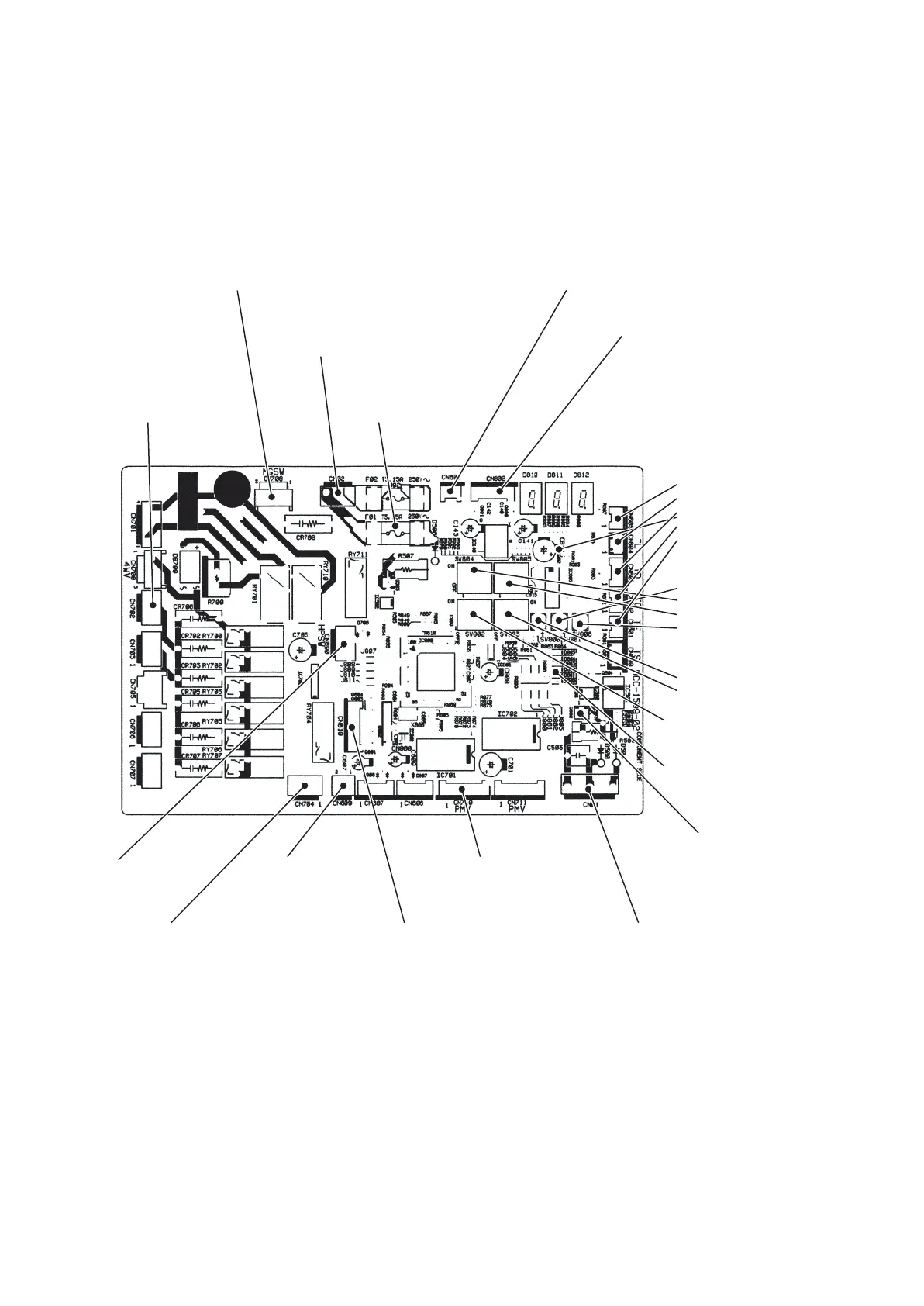
7-1-3. Print Circuit Board, MCC-1599 (Interface (CDB))
CN700
(Yellow)
4-way valve connector
F01
Power supply protective fuse
(250V, 3.15A)
CN690
(Green)
High-pressure
switch connector
CN609
(Blue)
Case thermostat connector
CN710
(White)
PMV1 Connector
CN704
(Blue)
Compressor ON
output connector
CN610
(Yellow)
Outside input connector
CN01
(White)
Inter-unit cable connector
CN02
(Red)
Connector for
MCC-1600 (CN10 and CN19)
CN802
(White)
Connector for MCC-1597 (CN504)
CN708
(Blue)
Connector for power relay coil
CN608
(White)
Connector for MCC-1600 (CN50)
Temp.sensor connector
CN604
(White) TL sensor
CN603
(White) TD sensor
CN602
(Yellow) TO sensor
CN601
(White) TE sensor
CN600
(White) TS sensor
Specific operation switch
SW801
SW804
SW805
SW806
Display select switch
SW800
SW803
Initial setting switch
SW802
Power-ON,check display LED
D800
to
D804
(Yellow)
D805
(Green)
Indoor/Outdoor communication
signal LED
D503
(Green), (Outdoor → Indoor)
D502
(Orange), (Indoor → Outdoor)
 Loading...