– 84 –
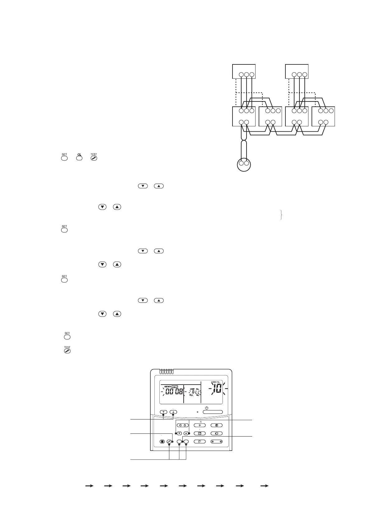
10-4. Address Setup (Manual setting from remote controller)
(Example of 2-lines cabling)
(Solid line: Cabling, Broken line: Refrigerant pipe)
For the above example, perform setting by
connecting singly the wired remote controller
without remote controller inter-unit cable.
Group address
Individual : 0000
Master unit : 0001
Sub unit : 0002
In case of group control
Outdoor
Indoor
A B
A B
1 2 3
Indoor
A B
1 2 3
Indoor
A B
1 2 3
Indoor
A B
1 2 3
1 2 3
Outdoor
1 2 3
Remote controller
Line address → 1
Indoor unit address → 1
Group address → 1
1
2
2
2
1
2
2
2
2
<Operation procedure>
1 2 3 4 5 6 7 8 9 10 11 END
1
3, 6, 9
END 11
2, 5, 8
4, 7, 10
E
TIM
TIMER
E
TE
RE
E
SWING
FI
VEN
M
D
ON
OF
NI
In case that addresses of the indoor units will be
determined prior to piping work after wiring work
• Set an indoor unit per a remote controller.
• Turn on power supply.
1 Push + + buttons simultaneously for
4 seconds or more.
2 (
←←
←←
← Line address)
Using the temperature setup
/
buttons, set the CODE No. to
1212
1212
12.
3 Using timer time / buttons, set the line
address.
4 Push button. (OK when display goes on.)
5 (
←←
←←
← Indoor unit address)
Using the temperature setup
/ buttons, set the CODE No. to
1313
1313
13.
6 Using timer time / buttons, set the line address to 1.
7 Push button. (OK when display goes on.)
8 (
←←
←←
← Group address)
Using the temperature setup
/ buttons, set the CODE No. to
1414
1414
14.
9 Using timer time / buttons, set Individual to
00000000
00000000
0000, Header unit to
00010001
00010001
0001, and Follower
unit to
00020002
00020002
0002.
10
Push button. (OK when display goes on.)
11
Push button.
Setup completes. (The status returns to the usual stop status.)
 Loading...