Basi
nsta
at
on and Operat
on G
de
T
Ser
es D
ta
olid
tate
o
t
tarters 1
1250A
15 | Page
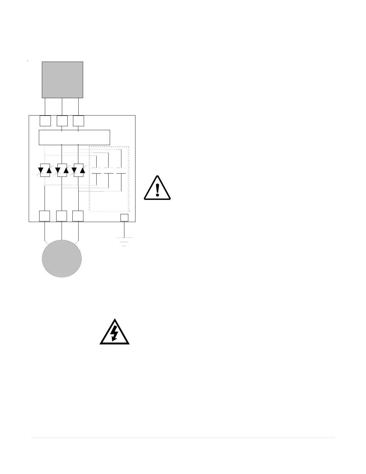
Figure 4.1:
TE Power Connections
Chapter 4 – Connections
4.1 Power Connections
Referring to local code standards for wire sizing and length, connect
power conductors to the unit input terminals marked L1, L2, L3 (R, S, T
for IEC users). Connection points for units of 160A and below are saddle
clamps suitable for stranded wire. Connection points for units of 210A
and above are bus tabs with pre-drilled holes (see section 2). Use
appropriate compression or mechanical lugs for termination to these bus
tabs. Avoid routing power wires over the control board or display.
Connect the motor leads to the unit terminals marked T1, T2 and T3 (U,
V and W for IEC users). If control power is present, but line power is
disconnected from L1, L2 and L3, the display will show [n3PH] indicating
“no 3 Phase”.
Caution!
Never interchange input and output connections to the
unit. This could cause excessive voltage in the control
logic circuit and may damage the unit.
4.1.1 Bypass Contactor
Bypass Contactors are integral (built-in) on all TE versions. See sections
1.2.3, 3.1.3.c and Appendix 4 for more details on contactor control and
overload protection details.
4.1.2 Power Factor Correction Capacitors
Power factor correction capacitors can be connected to motors controlled
by TE Series starters; however they must be off-line during ramping.
Connect PFC capacitors to the Line side of the starter with a separate
capacitor control contactor.
WARNING!
Never connect power factor correction capacitors on the load side of
the unit. The SCRs will be seriously damaged if capacitors are
located on the load side.
4.1.3 Grounding
Connect the ground cable to the ground terminal as labeled on the unit.
Refer to the National Electrical Code or your local Code for the proper
ground wire sizing and be sure that the ground connector is connected to
earth ground. In ungrounded systems, it is not necessary to connect a
ground to the unit however local codes should always be consulted.
Integral
Bypass
Contactor
TE Starte
.
Disconnect
o
Circuit
Breake
Solid State.
Over Load
.
MTR
G
R /
L1
T
L3
S
L2
U /
T1
W
T3
/
T2
Buy: www.ValinOnline.com | Phone 844-385-3099 | Email: CustomerService@valin.com

 Loading...


