E6581386
H-12
8
(Continued)
Commun
ication
No.
Item displayed
Key
operated
LED
display
Description
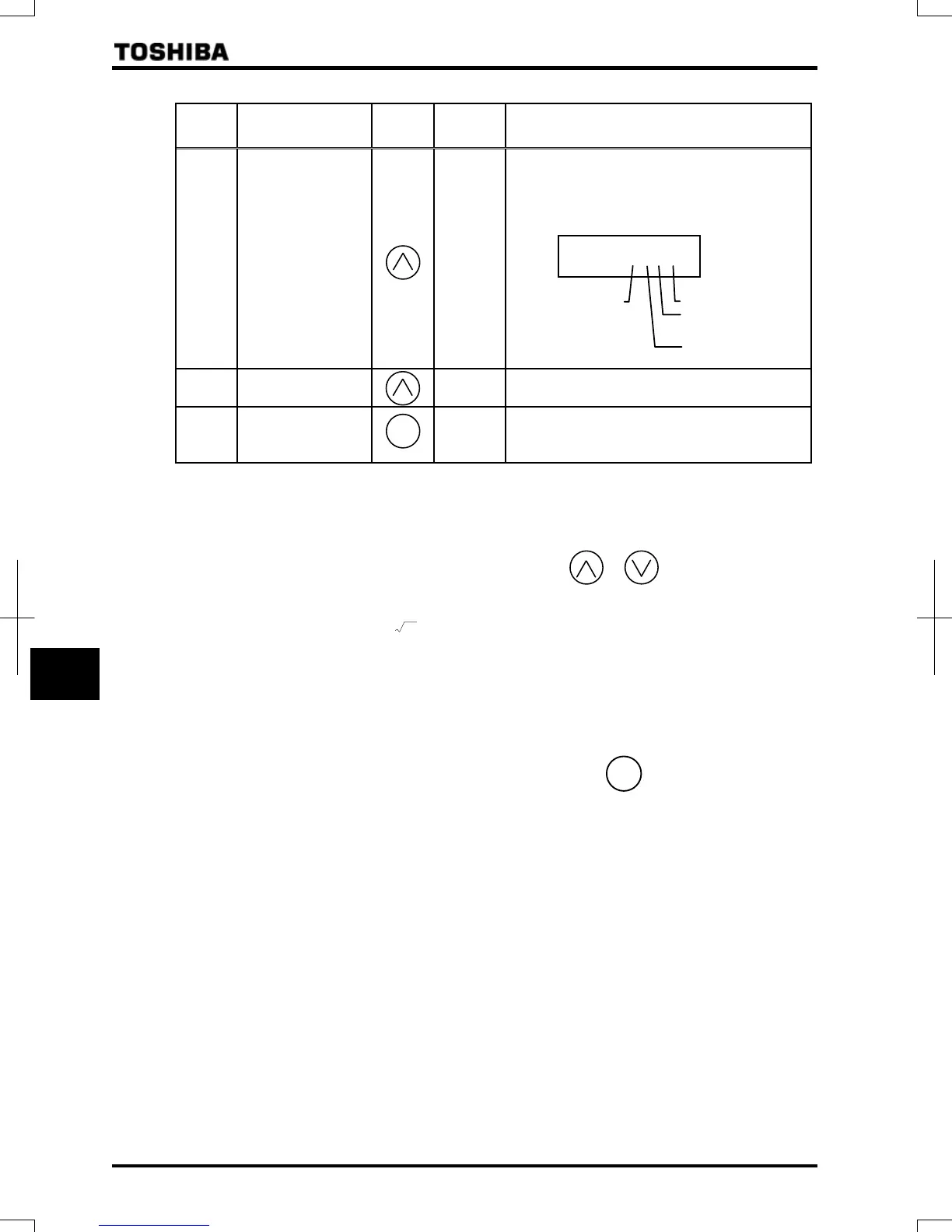
FE79
Part replacement
alarm information
The ON/OFF status of each of the cooling fan, circuit
board capacitor, main circuit capacitor or part
replacement alarm of cumulative operation time is
displayed in bits.
ON:
OFF:
FE14
Cumulative operation
time
The cumulative operation time is displayed.
(Indication of 0.1 represents 10 hours.)
- Default display mode
×2
Status monitor mode (The code blinks if a trip occurs.)
Reverts to the first trip indication.
Note 1: If trouble occurs while the CPU is being initialized after the inverter is turned on or reset, the trip record
retaining function does not record it but displays a status monitor item.
Note 2: Contents of status indications of *1, *2, *3, and *4 can be selected from about 40 kinds of information.
Contents of status indications that are set up at ~ (status monitor 1 to 4 display mode) are
displayed.
Note 3: Items displayed when a trip occurs can be changed by pressing or key.
Note 4: You can switch between % and A (ampere)/V (volt), using the parameter (current/voltage unit
selection).
Note 5: The input voltage displayed is 1/
2
times as large as the rectified DC input voltage.
Note 6: The number of bars displayed varies depending on the setting of (logic output/pulse train output
selection). The bar representing the OUT1 terminal is displayed only when logic output function is assigned to
it.
If =:The bar representing OUT1 is displayed.
If =:The bar representing OUT1 is not displayed.
Note 7: Past rip records are displayed in the following sequence: 1 (latest trip record)
234 (oldest trip record).
If there is no trip record, is displayed.
Details on past trip record 1, 2, 3 or 4 can be displayed by pressing the key when past trip 1, 2, 3 or 4
is displayed.
For more details, refer to Section 8.2.2.
Note 8: The time elapsed before an end of part replacement alarm is issued is calculated from the average yearly
ambient temperature, operation time and load current entered using , and it is no more than an
estimation, and therefore it should be used for reference purposes only.
Note 9: The cumulative operation time increments only when the machine is in operation.
Note 10: At the occurrence of a trip, maximum values are not always recorded and displayed for reasons of detecting
time.
ENT
Cooling fan
Cumulative
operation time
Control circuit board
capacitor
Main circuit capacitor
MODE
[Note 9]
[Note 8]
 Loading...