1. The manufacturer has a policy of continuous product and product data improvement and
reserves the right to change design and specications without notice. Always check the unit
nameplate and wiring diagram for the actual unit requirements.
2. The fuse is located on the main electrical board.
3. A dedicated indoor unit disconnect switch and power supply circuit may need to be installed
if local codes or jurisdictions require it. Otherwise, the indoor unit is powered directly from the
outdoor unit.
4. Install a separate disconnect at the outdoor unit. The power supply, wiring and grounding of
equipment must comply with National, State and/or local codes. The power supply must match
with the equipment nameplate specication.
5. Improperly installed and grounded eld wiring poses re and electrocution hazards. For
high voltage connections, exible electrical conduit is recommended whenever vibration
transmission may create a noise problem within the structure. To avoid these hazards you
MUST follow requirements for eld wiring installation and grounding as described in the
National Electrical Codes (NEC) and your State and/or local electrical codes. All eld wiring
MUST be performed by qualied personnel. Failure to follow these requirements could result in
death or serious injury.
6. The wiring, including the ground wire, between the indoor and outdoor units should be at least
14 AWG, 600 volt rated, type stranded wire, with an absolute maximum length of 230 feet
(70m). Type SO cable (temporary wire) is not recommended. Shorter lengths result in more
robust communication between the indoor and outdoor unit. Please select an appropriate
length for the installation conditions. The wires cannot be cut and spliced together.
7. For the wired controller: The standard length of control wire is 25 feet (7.6m). If extended
length is required, please refer to the wired control installation manual for splicing instructions.
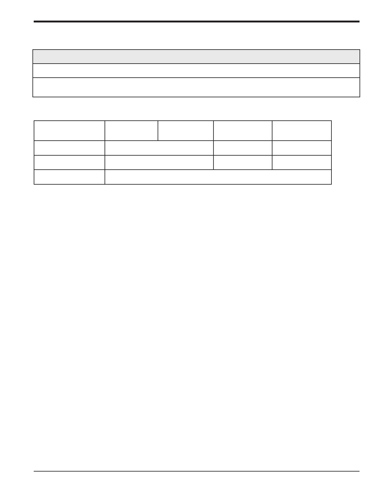
Heat Pump Models M4THS1809 M4THS1812 M4THS1818 M4THS1824
MOP 15 25 30
MCA 9 16 20
Power Supply 208/230V, 60Hz, 1phase
Electrical Requirements
Electrical Connections
CAUTION
Improper operation may lead to personal injury or property damage.
Size the power supply wiring according to the NEC, local code and the MCA indicated on the unit
nameplate.
88-M4MHW18-1C-EN 27
Installer's Guide
 Loading...