Note: A "Jumper Cap" may be used to determine fan speed and the swing angle of horizontal louver
for this model. The unit will not operate without the correct jumper cap. If "Jumper Caps" are installed
on the original electrical board, they must be removed and installed on a replacement electrical
board.
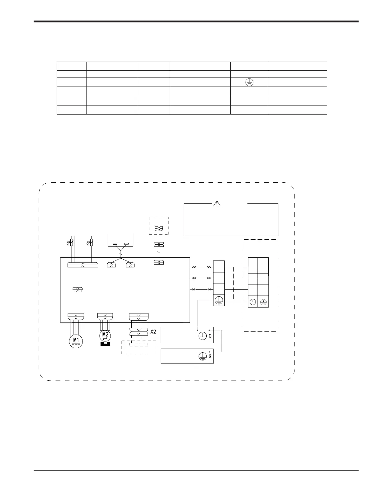
Wiring Diagrams
Color Key
NOTE: The wiring diagrams in this guide are included as a reference. The manufacturer
has a policy of continuous product and product data improvement and reserves the
right to change design and specications without notice. Always check the unit
nameplate and wiring diagram for the actual unit requirements.
Symbol Symbol Color Symbol Symbol Color Symbol Name
WH White GN Green COMP Compressor
eriw gniduorGnworBNBwolleYEY
RD Red BU Blue
YE/GN Yellow/Green BK Black
VT Violet OG Orange
n
Indoor Unit 9K, 12K,
L2
L
1
2
3
N(1)
TERMINAL
BLOCK
STEPPING
CAP
BLOCK
TERMINAL
EVAPORATOR
FAN MOTOR
JUMP
AP2: MAIN BOARD
YEGN
BK
BN
YEGN
N
3
2
N(1)
XT1
BU
AC-L
COM-OUT
COM-MANUAL
CONNECTOR
AP3
WIRED
MOTOR
OUTDOOR UNIT
T-SENSORDISP2 DISP1
RT1
AP1
ROOM
TUBE
TEMP.SENSOR
TEMP.SENSOR
DISPLAY BOARD
RECEIVER AND
RT2
DC-MOTOR
SWING-UD
ELECTRIC BOX
CABLE
CONTROLLER
WARNING
WIFI
WIFI MODULE
OPTIONAL
Please don't touch any electronic
component and terminal when the
machine is running , stopping or has
been powered off for less than 3
minutes to prevent electric shock !
6361000013301
88-M4MHW18-1C-EN 31
Installer's Guide
 Loading...