Page 17
Installer’s Guide
FIELD DUCT
UNIT DUCT
FLANGE
UNIT BASE
AIR PROOF
THIS SEAM
FIELD DUCT
UNIT DUCT
FLANGE
UNIT BASE
AIR PROOF
THIS SEAM
FIELD
DUCT
UNIT DUCT FLANGE
UNIT BASE
AIR PROOF
THIS SEAM
FIELD DUCT
UNIT DUCT
FLANGE
UNIT BASE
NOT RECOMMENDED
WATERPROOF SEAM
WITH BUTYL OR
SILICONE
DOWNFLOW
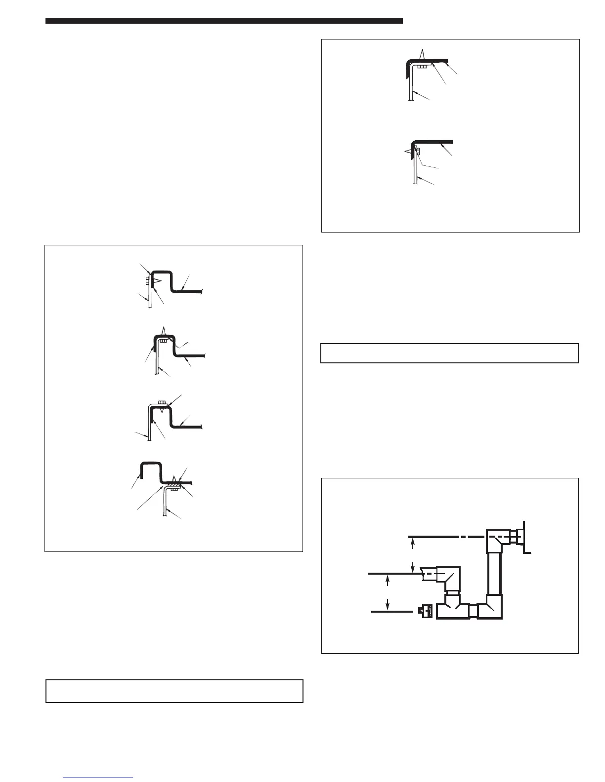
Attaching Horizontal Ductwork to Unit
All conditioned air ductwork should be insulated to minimize
heating and cooling duct losses. Use a minimum of two (2) inches
of insulation with a vapor barrier. The outside ductwork must be
weatherproofed between the unit and the building. See Figure 16.
When attaching ductwork to a horizontal unit, provide a flexible
watertight connection to prevent noise transmission from the unit to
the ducts. The flexible connection must be indoors and made out
of heavy canvas.
Note: Do not draw the canvas taut between the solid ducts.
Attaching Downflow Ductwork to Roof Curb
Supply and return air flanges are provided on the roof curb for easy
duct installation. All ductwork must be run and attached to the curb
before the unit is set into place.
Attaching Downflow Ductwork to Roof Frame
Follow these guidelines for ductwork construction:
Connections to the unit should be made with three inch canvas
connectors to minimize noise and vibration transmission.
Elbows with turning vanes or splitters are recommended to mini-
mize air noise and resistance.
The first elbow in the ductwork leaving the unit should be no closer
than two (2) feet from the unit, to minimize noise and resistance.
To prevent leaking, do not attach the ductwork to the bottom of the
unit base. Refer to the bottom example in Figure 15.
Condensate Drain Piping
A 3/4-inch female NPT condensate drain connection is provided on
the evaporator access panel end of the unit. Provide a trap and fill
it with water before starting the unit to avoid air from being drawn
through. Follow local codes and standard piping practices when
running the drain line. Pitch the line downward away from the unit.
Avoid long horizontal runs. See Figure 17.
NOTE: Do not use reducing fittings in the drain lines.
The condensate drain must be:
● Made of 3/4" pipe size.
● Pitched 1/4" per foot to provide free drainage to convenient drain
system.
● Trapped.
● Must not be connected to a closed drain system unless the trap
is properly vented.
Ductwork Installation
Figure 17. Typical Condensate Drain Piping
Figure 15. Attaching Down Airflow Ductwork
Figure 16. Attaching Horizontal Airflow Ductwork
FIELD DUCT
UNIT EXTERIOR
WEATHERPROOF
THIS SEAM
FIELD DUCT
UNIT EXTERIOR
WEATHERPROOF
THIS SEAM
3
/4" PVC OR COPPER
TUBING AND FITTINGS
1-1/2"
MIN.
1-1/2"
MIN.
 Loading...