.
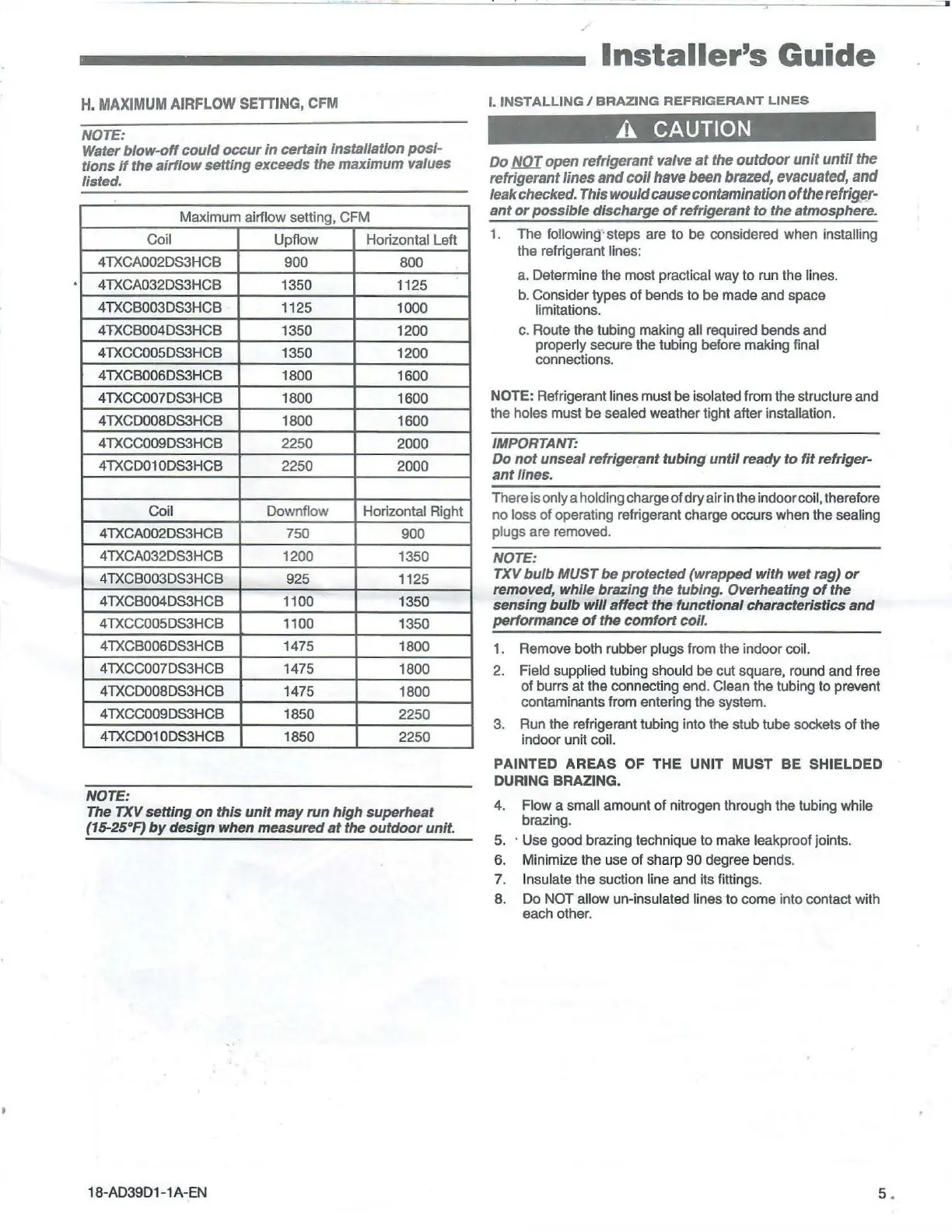
H.
MAXIMUM
AIRFLOW
SETTING, CFM
NOTE:
Water
blow-off
could
occur
In certain Installation posi-
tions
if
the
airflow
setting exceeds the maximum values
listed.
Maximum airflow setting, CFM
Coil
Upflow
Horizontal Left
4TXCA002DS3HCB
900 800
4TXCA032DS3HCB 1350
1125
4TXCB003DS3HCB 1125
1000
4TXCB004DS3HCB
1350
1200
4TXCC005DS3HCB 1350
1200
4TXC8006DS3HCB
1800 1600
4TXCC007DS3HCB 1800 1600
4TXCD008DS3HCB 1800
1600
4TXCC009DS3HCB
2250
2000
4TXCD01 ODS3HCB
2250 2000
Coil
Downflow
Horizontal Right
4TXCA002DS3HCB
750 900
4TXCA032DS3HCB 1200 1350
4TXCB003DS3HCB
925
1125
4TXCB004DS3HCB 1100
1350
4TXCC005DS3HCB 1100
1350
4TXCB006DS3HCB
1475
1800
4TXCC007DS3HCB
1475
1800
4TXCD008DS3HCB
1475 1800
4TXCC009DS3HCB 1850 2250
4TXCD01 ODS3HCB 1850 2250
NOTE:
The
TXV setting
on
this
unit
may
run
high
superheat
(15-25°F}
by
design when measured
at
the
outdoor
unit.
18
-AD39D1 -1 A-EN
Installer's
Guide
I.
INSTALL
I
NG/BRAZING
REFRIGERANT
LINES
A CAUTION
Do
1!KJI
open refrigerant valve
at
the
outdoor
unit
until
the
refrigerant
lines
and
coil
have been brazed, evacuated,
and
leak checked. This would cause contamination
of
the refriger-
ant
or
possible discharge
of
refrigerant
to
the atmosphere.
1.
The
following· steps are to be considered when installing
the refrigerant lines:
a. Determine the most practical way
to
run the lines.
b.
Consider types
of
bends to
be
made and space
limitations.
c. Route the tubing making
all required bends and
properly secure the tubing before making final
connections.
NOTE: Refrigerant
lines must be isolated from
the
structure and
the
holes must
be
sealed weather tight after installation.
IMPORTANT:
Do
not
unseal refrigerant tubing
until
ready
to
fit
refriger-
ant
lines.
There is only a holding charge
of
dry air in the indoor coil, therefore
no
loss
of
operating refrigerant charge occurs when the sealing
plugs
are removed.
NOTE:
TXV bulb MUST be protected (wrapped
with
wet rag)
or
removed, while brazing the tubing. Overheating
of
the
sensing
bulb
will
affect the functional characteristics
and
performance
of
the
comfort
coil.
1.
Remove both rubber plugs from the indoor coil.
2. Field supplied tubing should be cut square, round and free
of
burrs at
the
connecting end. Clean the tubing
to
prevent
contaminants from entering the system.
3. Run the refrigerant tubing into the stub
tub
e sockets
of
the
indoor unit
coil.
PAINTED
AREAS
OF
THE
UNIT
MUST
BE
SHIELDED
DURING BRAZING.
4. Flow a small amount of nitrogen through the tubing while
brazing.
5.
· Use good brazing technique to make leakproof joints.
6. Minimize the use
of
sharp
90
degree bend
s.
7. Insulate
the
suction line and its fittings.
8. Do
NOT allow un-insulated lines to come into contact with
each other.
5.
 Loading...