18
18-EB41D1-1C-EN
Attaching Horizontal Ductwork to Unit
All conditioned air ductwork should be insulated to
minimize heating and cooling duct losses. Use a
minimum of two (2) inches of insulation with a vapor
barrier. The outside ductwork must be weatherproofed
between the unit and the building.
When attaching ductwork to a horizontal unit, provide a
flexible watertight connection to prevent noise
transmission from the unit to the ducts. The flexible
connection mmuusstt be indoors and made out of heavy
canvas.
NNoottee:: Do not draw the canvas taut between the solid
ducts.
Figure 4. Attaching Horizontal Airflow Ductwork
FIELD DUCT
UNIT EXTERIOR
WEATHERPROOF
THIS SEAM
FIELD DUCT
UNIT EXTERIOR
WEATHERPROOF
THIS SEAM
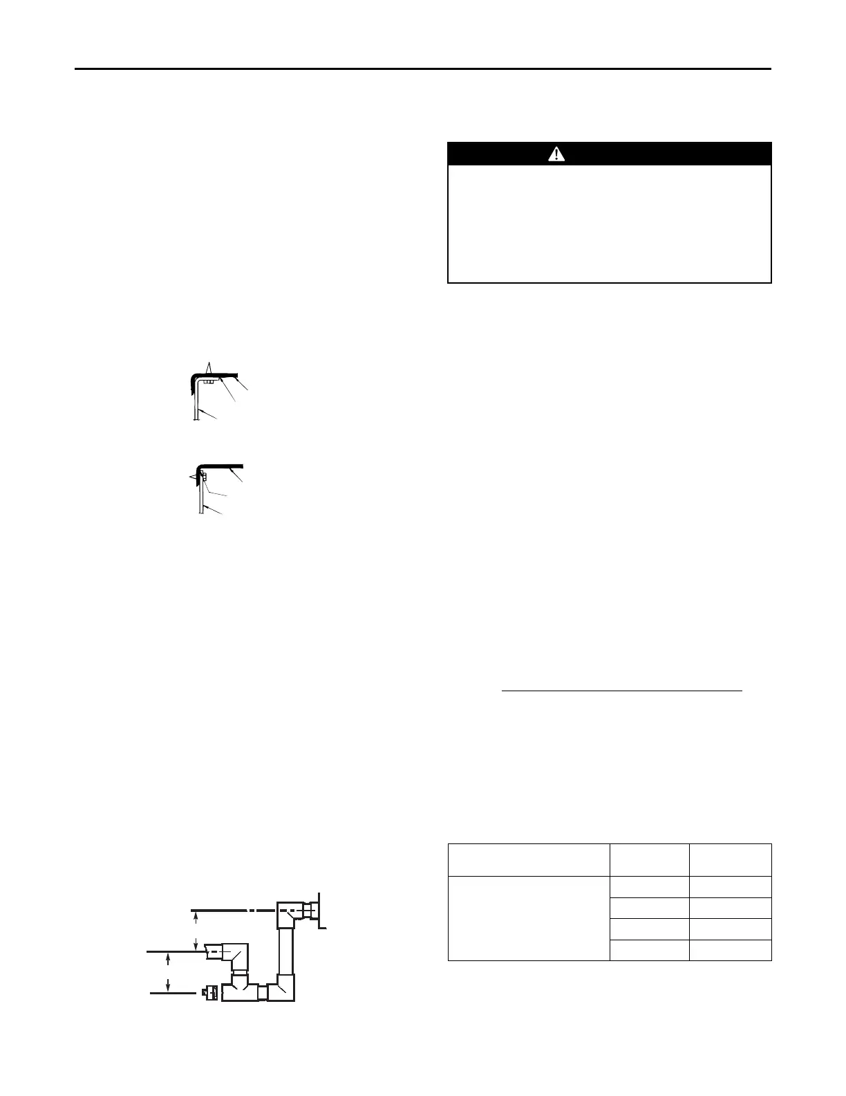
Condensate Drain Piping
A 3/4-inch female NPT condensate drain connection is
provided on the evaporator access panel end of the
unit. Provide a trap and fill it with water before starting
the unit to avoid air from being drawn through. Follow
local codes and standard piping practices when
running the drain line. Pitch the line downward away
from the unit. Avoid long horizontal runs. See Figure
5, p. 18.
NNoottee:: Do not use reducing fittings in the drain lines.
The condensate drain must be:
• Made of 3/4” pipe size
• Pitched 1/4” per foot to provide free drainage to
convenient drain system
• Trapped
• Must be connected to a closed drain system unless
the trap is properly vented
Figure 5. Typical Condensate Drain Piping
3
/4" PVC OR COPPER
TUBING AND FITTINGS
1-1/2" MIN.
1-1/2" MIN.
Gas Piping Installation
WWAARRNNIINNGG
FFIIRREE OORR EEXXPPLLOOSSIIOONN HHAAZZAARRDD!!
FFaaiilluurree ttoo ffoollllooww tthhee ssaaffeettyy wwaarrnniinngg eexxaaccttllyy ccoouulldd
rreessuulltt iinn sseerriioouuss iinnjjuurryy,, ddeeaatthh,, oorr pprrooppeerrttyy
ddaammaaggee..
UUssee aa ccoommmmeerrcciiaallllyy aavvaaiillaabbllee ssooaapp ssoolluuttiioonn mmaaddee
ssppeecciiffiiccaallllyy ffoorr tthhee ddeetteeccttiioonn ooff lleeaakkss ttoo cchheecckk aallll
ccoonnnneeccttiioonnss..
IImmppoorrttaanntt:: Before making the gas pipe connection,
give serious consideration to providing the
clearance necessary to remove the access
panels on the unit (e.g., economizer and
filter access panels).
NNoottee:: In the absence of local codes, the installation
must conform with American National Standard–
Z223.1–National Fuel Gas Code, Latest Revision.
The available gas supply must agree with the required
gas supply marked on the unit nameplate. Minimum
permissible gas supply pressure for purpose of input
adjustment must be at least 7.0 in. w. c. (inches water
column) for natural gas and 11 in. w. c. for LP Gas.
PPiippee DDeelliivveerryy SScchheedduullee
NNoottee:: The following procedure and tables apply to
Natural Gas oonnllyy.
1. Obtain from the gas company the heating value and
specific gravity of the gas delivered.
2. Determine the exact length of pipe needed.
3. Read BTUH input nameplate on the furnace.
4. Use the multiplier opposite the specific gravity of
the gas given in Multiplier Table and insert in the
following formula:
Furnace Input in BTUH
Gas Heat Contne in BTU/Cu. Ft. X Multiplier
CFH =
5. Use the Table 9, p. 19 and select the pipe length
nearest to calculated size.
6. Follow this line vertically down to the exact CFH
found in Step 4 above or the next highest value.
7. Read horizontally to the left of this column for the
required pipe size diameter.
Table 8. Specific Gravity Multiplier
SPECIFIC
GRAVITY
MULTIPLIER
MULTIPLIERS TO BE USED
WHEN THE SPECIFIC GRAVITY
OF THE GAS IS OTHER THAN
0.060
0.50 1.10
0.55 1.04
0.60 1.00
0.65 0.962
NNoottee:: If this is an LP Gas application, consult your LP
Gas supplier for pipe sizes and deliveries.
UUnniitt IInnssttaallllaattiioonn
 Loading...