18-EB41D1-1C-EN
21
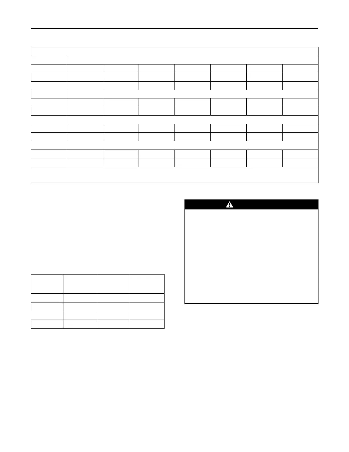
High Altitude Derate Chart Nat.
Unit Input Altitude (In Feet)
115k 2001 3000 4000 5000 6000 7000 8000
High stage
112100 104100 96200 88100 86900 85600 85100
Low stage
84000 78100 72100 66100 65100 64200 63800
90k
High stage
87700 81500 75200 69000 68000 67000 66500
Low stage
65700 61100 56400 51700 51000 50200 49900
70k
High stage
68200 63300 58500 53600 52900 52100 51800
Low stage
51100 47600 43900 40200 39600 39100 38800
60k
High stage
58500 54300 50100 46000 45300 44700 44300
Low stage
43800 40700 37600 34500 34000 33400 33200
Inputs shown are with factory orifices @ 3.5"WC (High Fire) 1.8"WC (Low Fire).
Natural Gas heating value of 950 btu/cuft.
For LP installations. Models that require #49 orifices, for altitudes from 7000 - 8000' orifices must be changed to #50.
Air Filter Installation
The packaged unit requires an air filter. The unit does
not come with a factory installed filter rack in it,
however, two filter frame accessories are offered that
will allow the installation of a filter within the unit,
BAYFLTR101 & BAYFLTR201. Otherwise a field
supplied filter rack must be installed by the installer in
the return duct work.
Affix the filter label supplied with the unit adjacent to
the filter area. Refer Table 12, p. 21 to determine filter
size.
Table 12. Filter Sizes
Unit
Nominal
CFM
Filter Size
(Sq Ft)
Filter
(a)
Resistance
(W.C.)
4YCZ*024 800 2.67 0.08
4YCZ*036 1200 4.00 0.08
4YCZ*048 1600 5.33 0.08
4YCZ*060 2000 6.67 0.08
(a)
Filters must be installed in the return air system. The above square
footages are based on 300 F.P.M. face velocity. If permanent filters
are used, size per mfg. Recommendation with clear resistance of
0.05" WC.
IImmppoorrttaanntt:: Air filters and media wheels or plates shall
meet the test requirements in UL 900.
Electrical Wiring
WWAARRNNIINNGG
IINNSSTTAALLLLAATTIIOONN WWAARRNNIINNGG —— HHIIGGHH
VVOOLLTTAAGGEE MMOOVVIINNGG PPAARRTTSS!!
FFaaiilluurree ttoo ffoollllooww tthhiiss WWaarrnniinngg ccoouulldd rreessuulltt iinn
pprrooppeerrttyy ddaammaaggee,, sseevveerree ppeerrssoonnaall iinnjjuurryy,, oorr
ddeeaatthh..
BBooddiillyy iinnjjuurryy ccaann rreessuulltt ffrroomm hhiigghh vvoollttaaggee
eelleeccttrriiccaall ccoommppoonneennttss,, ffaasstt mmoovviinngg ffaannss,, aanndd
ccoommbbuussttiibbllee ggaass.. FFoorr pprrootteeccttiioonn ffrroomm tthheessee
iinnhheerreenntt hhaazzaarrddss dduurriinngg iinnssttaallllaattiioonn aanndd sseerrvviicciinngg,,
tthhee mmaaiinn ggaass vvaallvvee mmuusstt bbee ttuurrnneedd ooffff aanndd tthhee
eelleeccttrriiccaall ssuuppppllyy mmuusstt bbee ddiissccoonnnneecctteedd.. IIff
ooppeerraattiinngg cchheecckkss mmuusstt bbee ppeerrffoorrmmeedd wwiitthh tthhee uunniitt
ooppeerraattiinngg,, iitt iiss tthhee tteecchhnniicciiaann’’ss rreessppoonnssiibbiilliittyy ttoo
rreeccooggnniizzee tthheessee hhaazzaarrddss aanndd pprroocceeeedd ssaaffeellyy..
NNoottee:: This unit is factory wired for 230V. See wiring
diagram for 208V conversion.
EElleeccttrriiccaall CCoonnnneeccttiioonnss
Electrical wiring and grounding must be installed in
accordance with local codes or, in the absence of local
codes, with the National Electrical Code ANSI/NFPA 70,
Latest Revision.
NNoottee:: For branch circuit wiring (main power supply to
unit disconnect), determine wire size for the
length of run using the circuit ampacity found on
the unit nameplate and the N.E.C.
For more than 3 conductors in a raceway or cable, see
the N.E.C. for derating the ampacity of each conductor.
UUnniitt IInnssttaallllaattiioonn
 Loading...