18-GF15D1-1B-EN
13
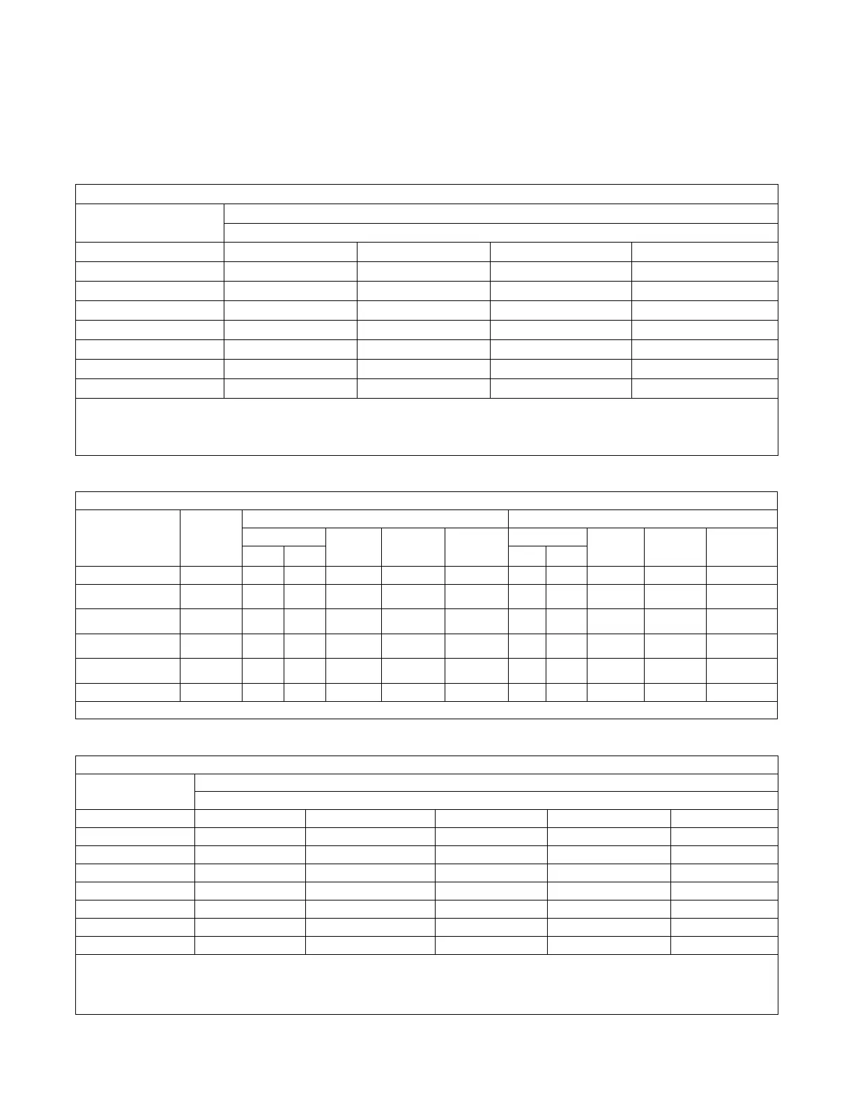
Performance and Electrical Data
Table 4. Air Flow Performance
A4AH5E19A1B30A
EXTERNAL STATIC
(in w.g)
AIRFLOW
Speed Taps: 208 – 230 VOLTS
High Med-High
Med † Low
0.1 1140 1078 930 851
0.2 1087 1017 870 796
0.3 1034 955 807 733
0.4 978 894 741 663
0.5 922 834 671 584
0.6 863 774 597 497
0.7 804 715 519 403
1. Values are with wet coil, no filter, and no heaters
2. CFM Correction for dry coil = Add 3%
3. † = Factory Setting
4. Low = Taps 1–2, Med = Tap 3, Med-High= Tap 4, High = Tap 5
Table 5. Electrical Data
A4AH5E19A1B30A
Heater Model No.
No. of
Circuits/
Phases
240 Volt 208 Volt
Capacity
Heater
Amps per
Circuit
Minimum
Circuit
Ampacity
Maximum
Overload
Protection
Capacity
Heater
Amps per
Circuit
Minimum
Circuit
Ampacity
Maximum
Overload
Protection
kW BTUH kW BTUH
No Heater 2.8 * 4 15 2.8 * 4 15
BAYHTR1504BRK
BAYHTR1504LUG
1/1
3.8 13100 16.0 24 25 2.9 9800 13.8 21 25
BAYHTR1505BRK
BAYHTR1505LUG
1/1
4.8 16400 20.0 29 30 3.6 12300 17.3 25 25
BAYHTR1508BRK
BAYHTR1508LUG
1/1
7.7 26200 32.0 44 45 5.8 19700 27.7 38 40
BAYHTR1510BRK
BAYHTR1510LUG
1/1
9.6 32800 40.0 54 60 7.2 24600 34.6 47 50
BAYHTR3510LUG
1/3
9.6 32800 23.1 32 35 7.2 24600 20.0 28 30
* = Motor Amps
Table 6. Air Flow Performance
A4AH5E31A1B30A
EXTERNAL STATIC
(in w.g)
AIRFLOW
Speed Taps: 208 – 230 VOLTS
High Med-High
Med † Med-Low Low
0.1 1192 1127 1070 995 940
0.2 1148 1079 1021 943 885
0.3 1103 1031 971 890 828
0.4 1057 980 919 834 767
0.5 1009 929 865 775 702
0.6 961 875 810 714 635
0.7 911 820 753 651 564
1. Values are with wet coil, no filter, and no heaters
2. CFM Correction for dry coil = Add 3%
3. † = Factory Setting
4. Low = Tap 1, Med-Low = Tap 2, Med = Tap 3, Med-High= Tap 4, High = Tap 5
 Loading...