Installer’s Guide
18-CD21D1-12
When the upflow furnace is installed in the hori-
zontal right or left application and a return duct
is attached to the top side as shown in Figure 11,
remove the filter from the furnace and install in a
remote location.
Do not install the filter in the return duct directly
above the furnace in horizontal applications.
When the upflow furnace is installed in the hori-
zontal right or left application and a close coupled
(less than 36") return duct is attached to the bot-
tom side of the furnace as shown in Figure 11, se-
curely attach a 1/2" mesh metal hardware cloth
protective screen to the inside bottom of the filter
grill to prevent personal injury from contact-
ing moving parts when reaching into the re-
turn opening to replace the filter.
Close coupled (less than 36") return (lter directly
beneath bottom side return) is not recommended
due to noise considerations.
Downflow Furnaces: Brackets are factory sup-
plied to mount filters in the return air duct work.
8. Connect the duct work to the furnace. See Outline
Drawing for supply and return duct size and loca-
tion. Flexible duct connectors are recommended
to connect both supply and return air ducts to the
furnace.
If only the front of the furnace is accessible, it is
recommended that both supply and return air ple-
nums are removable.
9. The horizontal installation of the upflow fur-
nace requires an external filter section. Do
NOT use the bottom return filter within the
furnace. Filter kits are available for horizon-
tal applications.
10. When replacing a furnace, old duct work should
be cleaned out. Thin cloths should be placed over
the registers and the furnace fan should be run for
10 minutes. Don’t forget to remove the cloths be-
fore you start the furnace.
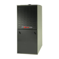
FILTER
REMOVE FILTER FROM UPFLOW
FURNACE WHEN RETURN DUCT IS
ATTACHED TO FURNACE TOP SIDE
(HORIZONTAL LEFT OR RIGHT AP-
PLICATIONS) AS SHOWN.
Close coupled (less than 36")
return (filter directly beneath bottom
side return) not recommended due to
noise considerations. If used, securely
attach 1/2" mesh metal hardware cloth
protective screen to the inside bottom
of filter grill.
q
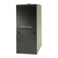
*SEE OUTLINE DRAWING
w
LOCATING
NOTCHES
PROVIDED
FOR SIDE
RETURN
CUTOUT
FRONT
of Furnace
*
*
*
*
CUT OUT
FOR
SIDE
FILTER
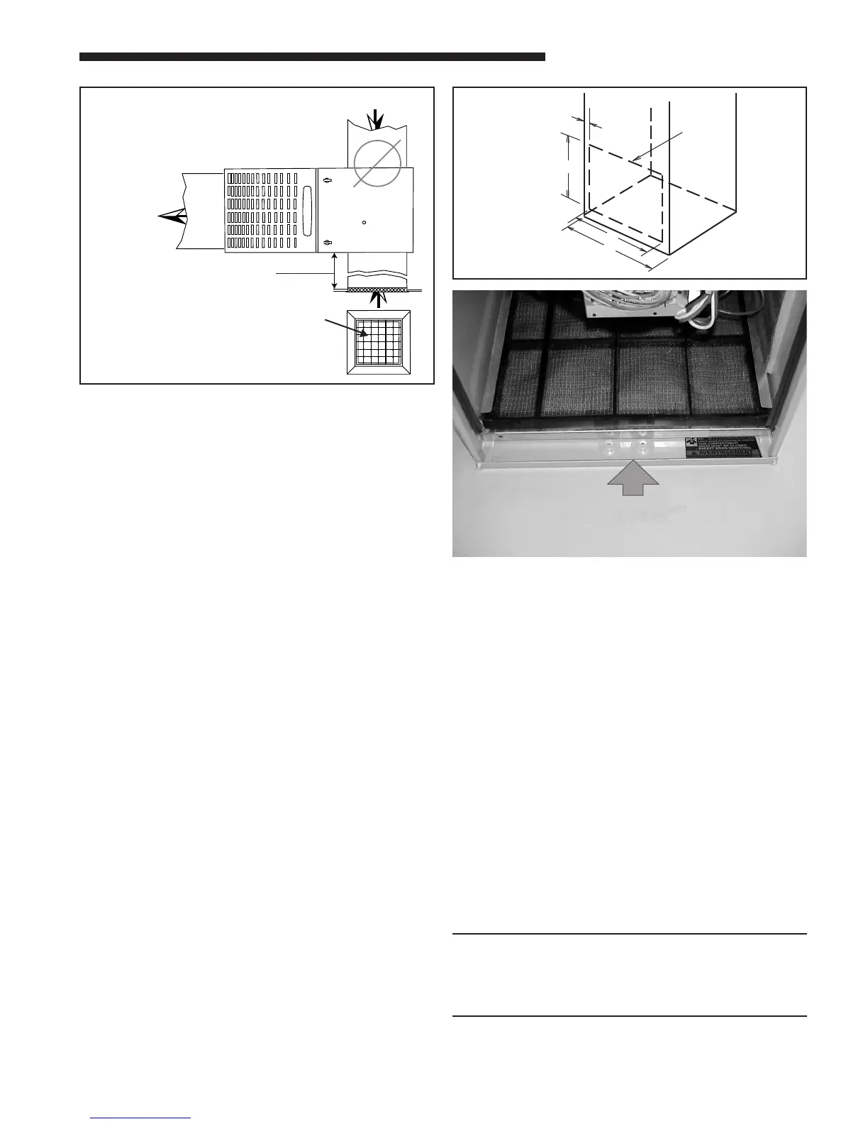
BOTTOM FILTER RACK INSTALLATION
Airflow
e
11. The bottom panel of the upflow furnace must be
removed for bottom return air. After removing the
filter, lay the furnace on its back. Remove the two
5/16" hex screws securing the front of the bottom
channel to the cabinet. Rotate the channel down-
ward (or remove by lowering the front edge of the
channel and pulling forward). Slide the bottom
return air panel out of the cabinet. Rotate the
front channel to its original position and reinstall
the two 5/16” screws.
RETURN AIR FILTERS
TYPICAL UPFLOW RETURN AIR
FILTER INSTALLATIONS
These furnaces require high velocity type air filters.
The filters may be installed within the furnace blower
compartment for UPFLOW furnaces in either a BOT-
TOM or SIDE (left side or right side) return air inlet.
Some filters may need to be trimmed for side or bottom
filter use.
NOTE:
For upflow 5 ton airflow models where the airflow
requirement exceeds 1800 CFM - Models will require
return air openings and filters on: (1) both sides, or (2)
one side and the bottom, or (3) just the bottom.
The furnace and the bottom lter rack, BAYRACK960,
installation can be seen in Figure 13.
 Loading...