15
Installation (Continued)
Rigging
A Rigging illustration and Center-of-Gravity dimensional
data table is shown in Figure 3-3. Refer to the typical unit
operating weights table before proceeding.
1. Rig the condensing unit as shown in Figure 3-3. Attach
adequate strength lifting slings to all four lifting brackets
in the unit base rail. Do not use cables, chains, or slings
except as shown.
2. Install spreader bars, as shown in Figure 3-3, to protect
the unit and to facilitate a uniform lift. The minimum dis-
tance between the lifting hook and the top of the unit
should be 7 feet.
3. Test-lift the unit to ensure it is properly rigged and bal-
anced, make any necessary rigging adjustments.
4. Lift the unit and position it into place.
Unit Isolation
To minimize unit sound and vibration transmission, one of
the following installation methods should be used:
1. Install the unit directly on an isolated (detached) concrete
pad or on isolated concrete footings located at each unit
load point.
2. Install the optional neoprene or spring isolators at each
mounting location. Refer to the following “Neoprene iso-
lators” or “Spring Isolator” section.
Neoprene Isolators
Install the neoprene isolators at each unit mounting (load)
point, using the following procedure:
1. Elevate the unit (one side at a time) to allow access to
the base rail mounting holes.
Note: Use solid type blocks, i.e. 4" X 4" wood
blocks or similar material to prevent collapsing.
Keep hands and other body limbs clear of elevated
base rail while installing isolators to prevent
personal injury.
2. Align the mounting holes in the base rail of the unit with
the holes in the top of the appropriate isolator. Refer to
Figure 3-4 for the appropriate isolator for each load point.
3. Install a 1/2" NC bolt (field supplied) through the base rail
of the unit into the threaded bolt hole of the isolator. Po-
sition the isolator to allow access to the mounting holes
in the base of the isolator, then tighten securely.
4. Lower the unit and isolator onto the mounting surface.
The maximum isolator deflection should be approxi-
mately 1/4 inch.
5. Secure the isolator to the mounting surface using the
base holes in the isolator.
6. Level the unit carefully. Refer to the “Leveling the Unit”
section.
7. After the unit is level, tighten the isolator base mounting
bolts to secure them to the mounting surface.
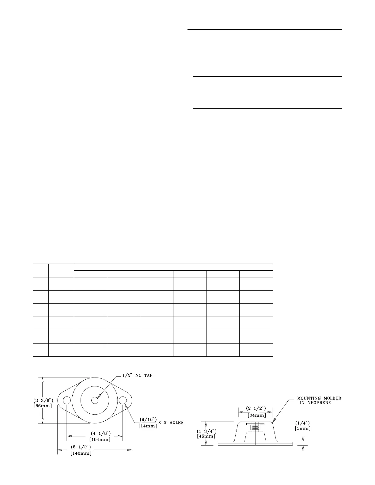
Figure 3-4
Typical Neoprene Isolator Selection & Location
Unit Fin Neoprene Isolator Part Number @ Mounting Location
Size Material Location 1 Location 2 Location 3 Location 4 Location 5 Location 6
C20 Al RDP-3-RED RDP-3-RED RDP-3-RED RDP-3-RED
Cu RDP-3-GRN RDP-3-RED RDP-3-RED RDP-3-RED
C25 Al RDP-3-RED RDP-3-RED RDP-3-RED RDP-3-RED
Cu RDP-3-GRN RDP-3-GRN RDP-3-RED RDP-3-RED
C30 Al RDP-3-RED RDP-3-GRN RDP-3-RED RDP-3-RED
Cu RDP-3-GRN RDP-3-GRN RDP-3-RED RDP-3-GRN
C40 Al RDP-3-RED RDP-3-RED RDP-3-RED RDP-3-RED RDP-3-RED RDP-3-RED
Cu RDP-3-GRN RDP-3-GRN RDP-3-GRN RDP-3-GRN RDP-3-GRN RDP-3-GRN
C50 Al RDP-3-GRN RDP-3-GRN RDP-3-GRN RDP-3-GRN RDP-3-RED RDP-3-RED
Cu RDP-3-GRN RDP-3-GRN RDP-3-GRN RDP-3-GRN RDP-3-GRN RDP-3-GRN
C60 Al RDP-3-GRN RDP-3-GRN RDP-3-GRN RDP-3-GRN RDP-3-GRN RDP-3-GRN
Cu RDP-3-GRN RDP-3-GRN RDP-3-GRN RDP-3-GRN RDP-3-GRN RDP-3-GRN
Notes:
1. Mounting locations correlate with those shown in point loading illustration.
 Loading...


