16
Spring Isolators
Install the spring isolators at each unit mounting (load) point
using the following procedure:
1. Elevate the unit (one side at a time) to allow access to
the base rail mounting holes.
Note: Use solid type blocks, i.e. 4" X 4" wood
blocks or similar material to prevent collapsing.
Keep hands and other body limbs clear of elevated
base rail while installing isolators to prevent
personal injury.
2. Align the mounting holes in the base rail of the unit with
the positioning pin in the top of the appropriate isolator.
Refer to Figure 3-5 for the appropriate isolator for each
load point.
3. Position the isolator to allow access to the mounting
holes in the base of the isolator.
4. Lower the unit onto the isolator. The positioning pin on
the isolator must engage into the hole of the base rail.
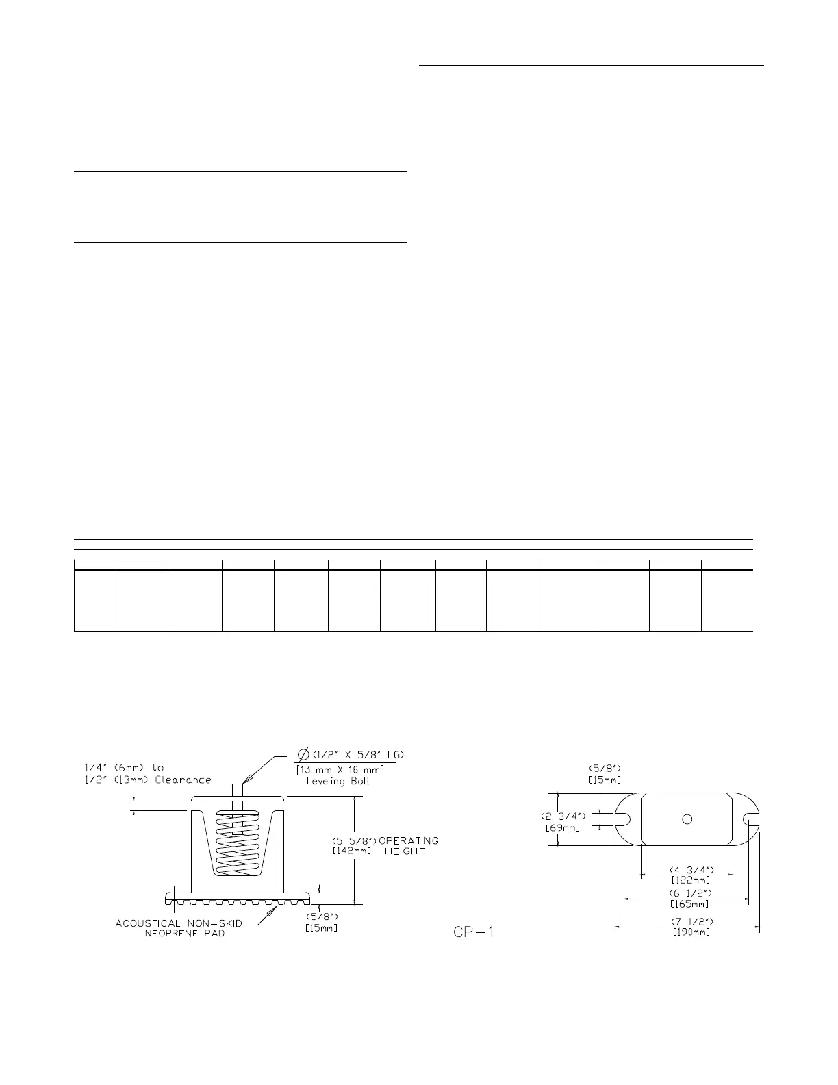
The clearance between the upper and lower isolator
housings should be approximately 1/4 to 1/2 inch. Refer
to Figure 3-5. A clearance greater than 1/2 inch indi-
cates that shims are required to level the unit. Refer to
the “Leveling the Unit” section.
5. Make minor clearance adjustments by turning the isola-
tor leveling bolt (Figure 3-5) clockwise to increase the
clearance and counterclockwise to decrease the clear-
ance. If proper isolator clearance cannot be obtained by
turning the leveling bolt, level the isolators themselves.
A 1/4 inch variance in elevation is acceptable.
6. Secure the isolator to the mounting surface using the
base holes in the isolator.
7. After the unit is level, tighten the isolator base mounting
bolts to secure them to the mounting surface.
Leveling the Unit
Before tightening the mounting bolts, level the unit carefully.
Use the unit base rail as a reference. Level the unit to within
1/4 inch over its entire length. Use shims if adjustable isola-
tors (neoprene) are not used.
If adjustable isolators (spring) are used, ensure that the
proper isolator housing clearance is maintained while lev-
eling the unit. Isolators are identified by color and/or an
isolator part number. Shims under the isolators may be re-
quired if the unit can not be leveled using the isolator lev-
eling bolt.
Figure 3-5
Typical Spring Isolator Selection & Location
Installation (Continued)
Unit Tons Al Cu Al Cu Al Cu Al Cu Al Cu Al Cu
C20 CP-1D-675 CP-1D-675 CP-1D-675 CP-1D-675 CP-1D-510 CP-1D-510 CP-1D-510 CP-1D-510
C25
CP-1D-675 CP-1D-675 CP-1D-675 CP-1D-675 CP-1D-510 CP-1D-510 CP-1D-510 CP-1D-675
C30
CP-1D-675 CP-1D-900 CP-1D-675 CP-1D-900 CP-1D-510 CP-1D-675 CP-1D-510 CP-1D-675
C40
CP-1D-675 CP-1D-900 CP-1D-675 CP-1D-675 CP-1D-675 CP-1D-675 CP-1D-675 CP-1D-675 CP-1D-675 CP-1D-675 CP-1D-510 CP-1D-675
C50
CP-1D-900 CP-1D-900 CP-1D-675 CP-1D-900 CP-1D-675 CP-1D-900 CP-1D-675 CP-1D-900 CP-1D-675 CP-1D-900 CP-1D-675 CP-1D-675
C60
CP-1D-900 CP-1D-900 CP-1D-900 CP-1D-900 CP-1D-900 CP-1D-900 CP-1D-900 CP-1D-675 CP-1D-900 CP-1D-675 CP-1D-900 CP-1D-675
Notes
1. Mounting locations correlate with those shown in point loading illustration.
2. The spring is marked with the full spring ID part # (ie CP-1D-900)
The isolator spring is color coded as follows;
CP-1D-510=Black, CP-1D-675=Dark Purple, CP-1D-900=Dark Green
3. Refer to the “Spring Isolator” section, step 4, for proper clearance.
Location 1
Spring Isolator Part Number @ Mounting Location
Location 2 Location 3 Location 4 Location 5 Location 6
 Loading...


