Troubleshooting Guide
CLCH-SVX014B-EN 31
VB1287 Sequence of Operations
1. A call for heat is initiated by the rooftop unit control
through a digital Modbus signal or the analog
thermostat.
2. The VB1287 control will then go through a system
check to ensure that the high temperature limit and
rollout switches are closed, the air pressure switch is
open, and the modulating valve is positioned correctly.
3. The control will then enter the pre-purge cycle, where
the inducer will run at the programmed purge
pressure. During this cycle, the control will look for the
air pressure switch to close and open at the correct
settings.
4. Once the system check and pre-purge cycles are
complete, the control will enter the ignition cycle.
a. The inducer will go to its “light off” setting (usually
high speed).
b. The DSI ignition module will be energized and the
spark ignitor will activate.
c. The safety valve will open, allowing gas flow.
d. The burners will ignite and the VB1287 control will
receive a signal from the flame sensor.
e. The spark ignitor will remain active for the duration
of the ignition cycle, regardless of flame status.
5. If flame is not established during the ignition cycle, the
control will repeat the pre-purge and ignition cycles up
to three times. After three failed ignition attempts, the
board will enter a 1 hour lockout.
6. Once flame has been established, the control will enter
a warm-up period to ensure flame stabilization and
reduce condensation in the heat exchanger.
7. After the warm-up period, the control will enter the run
cycle. During the run cycle, the burner firing rate is
determined by the heat demand received by the
control via a Modbus signal or the analog thermostat.
Two firing stages, High or Low, are available.
Note: If the control is paired with a split manifold, steps 1
through 6 pertain to the primary burners. Once the
control exits the warm-up period and the firing rate
is dictated by the rooftop control, the control will
ignite the secondary burners and step High or Low
the primary burners based on the demand for heat.
8. The run cycle will continue until any of the following
conditions are met.
a. The call for heat is terminated.
b. Any of the safety devices (high limit, air pressure,
rollout, etc.) are triggered.
c. The control reaches it’s maximum run time of 6
hours. If this condition is reached, the control will
terminate the run cycle, continue through the
proper sequence of operations, and then
immediately enter the system check and pre-purge
cycles to prepare for re-ignition, assuming
conditions A and B haven't been met.
9. Once the run cycle has terminated, the redundant
safety valve will close, the modulating valve will return
to its set position, and the draft inducer will ramp up to
its “light-off” setting for a 45 second post-purge cycle.
10. After the conclusion of the post-purge, the control will
enter the “OFF” state. All system outputs are de-
energized but all safety devices are still monitored.
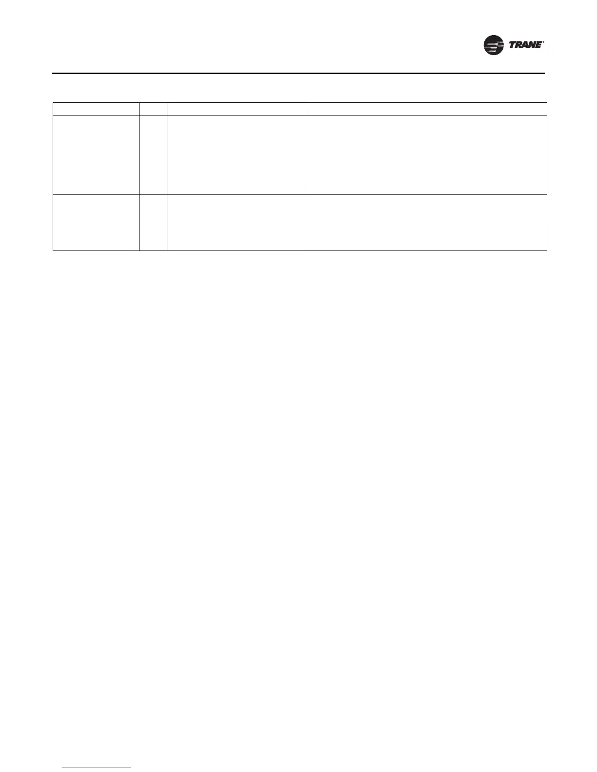
ePRIMARY_LIMIT 51
Primary limit and/or rollout switches are
open
1. Determine which switches are open using an OHM meter.
2. If limit switch is open, check temperature rise and airflow over the
heat exchanger.
3. If high limit does not reset with proper airflow, change limit.
4. If rollout switch is open, check for flue vent blockage or air leaks
in the cabinet.
5. Reset the rollout switch and observe the flame for signs of rolling
out.
eGAS_VALVE_HI_PRIME
eGAS_VALVE_HI_SPLIT
eGAS_VALVE_HI_PRIME
_SPLIT
15
25
35
Prime burner staging failure. Gas valve is
in the incorrect state.
Split burner staging failure. Gas valve is in
the incorrect state.
Both the split and primary gas valves are
in the incorrect state.
1. Check gas valve wiring.
2. Check for shorts in 24V circuit.
3. Replace control.
Table 7. Troubleshooting guide for VB1287 (continued)
Failure Code Description of Symptom Actions
 Loading...


