18-CD20D1-18 13
Installer’s Guide
GENERAL VENTING INSTRUCTIONS
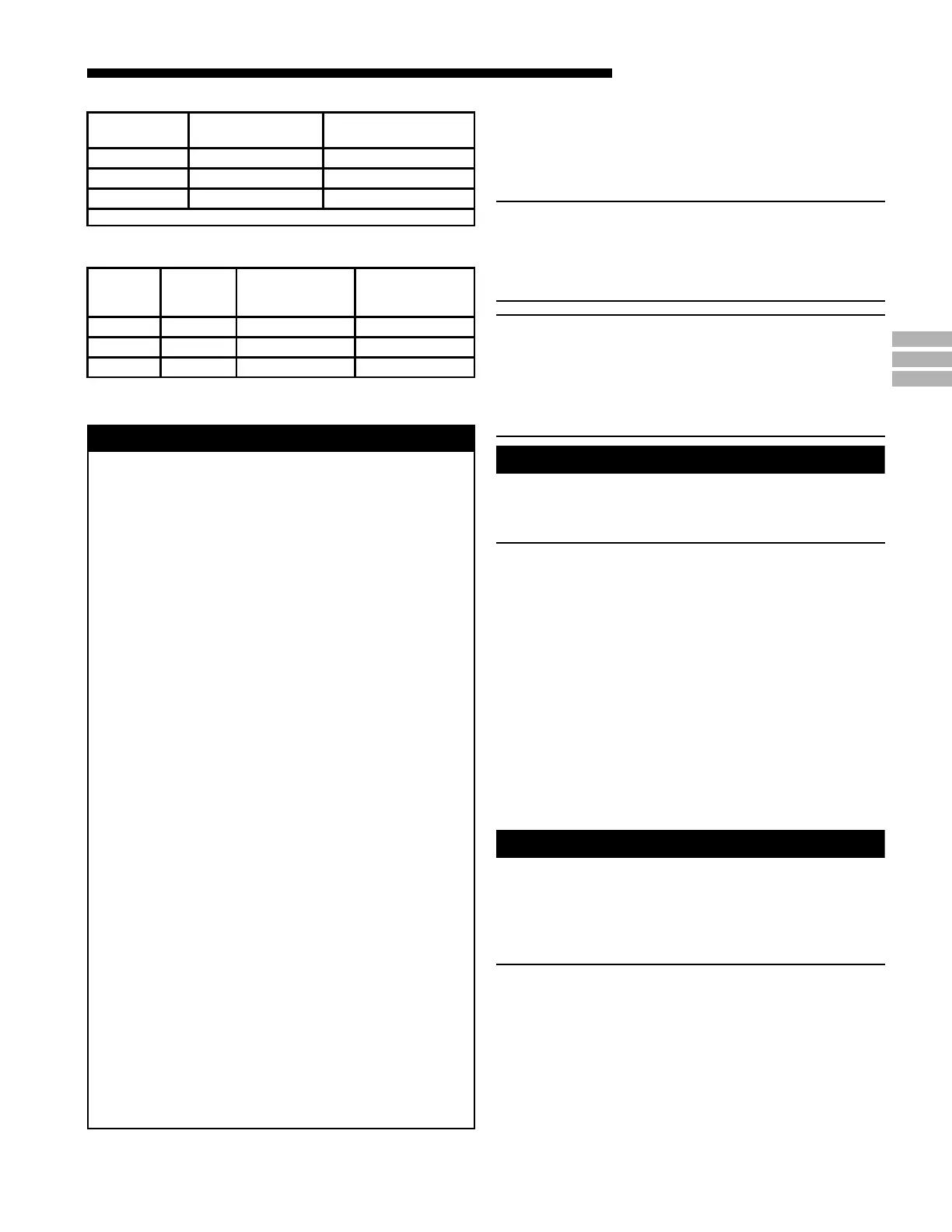
CARBON MONOXIDE POISONING HAZARD
Failure to follow the steps outlined below for each
appliance connected to the venting system being
placed into operation could result in carbon monoxide
poisoning or death.
The following steps shall be followed for each appliance
connected to the venting system being placed into
operation, while all other appliances connected to the
venting system are not in operation:
1. Seal any unused openings in the venting system.
2. Inspect the venting system for proper size and
horizontal pitch, as required in the National Fuel Gas
Code, ANSI Z223.1/NFPA 54 or the CAN/CGA B149
Installation Codes and these instructions. Determine
that there is no blockage or restriction, leakage,
corrosion and other deficiencies which could cause an
unsafe condition.
3. As far as practical, close all building doors and
windows and all doors between the space in which the
appliance(s) connected to the venting system are
located and other spaces of the building.
4. Close fireplace dampers.
5. Turn on clothes dryers and any appliance not
connected to the venting system. Turn on any exhaust
fans, such as range hoods and bathroom exhausts, so
they are operating at maximum speed. Do not operate
a summer exhaust fan.
6. Follow the lighting instructions. Place the appliance
being inspected into operation. Adjust the thermostat
so appliance is operating continuously.
7. If improper venting is observed during any of the above
tests, the venting system must be corrected in
accordance with the National Fuel Gas Code,
ANSI Z221.1/NFPA 54 and/or CAN/CGA B149
Installation Codes.
8. After it has been determined that each appliance
connected to the venting system properly vents where
tested as outlined above, return doors, windows,
exhaust fans, fireplace dampers and any other gas-fired
burning appliance to their previous conditions of use.
WARNING
!
TABLE 5
TABLE 6
CABINET
WIDTH
RETURN
DUCT
WIDTH
FILTER ACCESS
OPENING -
DIMENSION "A"
FILTER ACCESS
OPENING -
DIMENSION "B"
17-1/2" 16-1/4" 15" 14"
21" 19-3/4" 19-1/2" 14"
24-1/2" 23-1/4" 22" 14"
CABINET
WIDTH
FILTER
SIZE
FILTER BRACKET
LOCATION *
17-1/2" 2 - 16X20X1 14-3/8"
21" 2 - 16X20X1 13-1/8"
24-1/2" 2 - 16X20X1 11-5/8"
* Location dimension is from end of duct to the screw holes for the bracket.
VENT PIPING
These furnaces have been classified as Fan-Assisted Combus-
tion System, Category I furnaces under the “latest edition”
provisions of ANSI Z21.47 and CAN/CGA 2.3 standards.
Category I furnaces operate with a non-positive vent static
pressure and with a flue loss of not less than 17 percent.
NOTE:
If desired, a side wall termination can be accomplished
through the use of an “add-on” draft inducer. The inducer
must be installed according to the inducer manufacturer’s
instructions. Set the barometric pressure relief to achieve
-0.02 inch water column.
NOTE: When the downflow furnace is vented through the
left side of the furnace cabinet using the provided cutout,
Type B vent piping must be used.
The furnace shall be connected to a factory built chimney
or vent complying with a recognized standard, or a ma-
sonry or concrete chimney lined with a lining material
acceptable to the authority having jurisdiction.
WARNING
!
Furnace venting into an unlined masonry chimney or
concrete chimney is prohibited. Failure to follow this
warning could result in property damage, personal injury,
or death.
VENTING INTO A MASONRY CHIMNEY
If the chimney is oversized, the liner is inadequate, or flue-
gas condensation is a problem in your area, consider using
the chimney as a pathway or chase for type “B” vent or flex-
ible vent liner. If flexible liner material is used, size the vent
using the “B” vent tables, then reduce the maximum capacity
by 20% (multiply 0.80 times the maximum capacity).
Masonry Chimney Kit BAYVENT800B may be used with
these furnaces (Upflow model furnaces only) to allow
venting into a masonry chimney. Refer to the BAYVENT800B
Installer’s Guide for application requirements.
Internal Masonry Chimneys
Venting of fan assisted appliances into a lined, internal
masonry chimney is allowed only if it is common vented with
at least one natural draft appliance; OR, if the chimney is
lined with type “B”, double wall vent or suitable flexible liner
material (See Table 7).
WARNING
!
The chimney liner must be thoroughly inspected to insure
no cracks or other potential areas for flue gas leaks are
present in the liner. Liner leaks will result in early deteriora-
tion of the chimney.
Failure to follow this warning could result in carbon monox-
ide poisoning or death.
 Loading...