18-CD20D1-18 19
Installer’s Guide
7. Changes can be made by adjusting the manifold pressure
(See Table 9), or changing orifices (orifice change may not
always be required). To adjust the manifold pressure:
a. Turn off all electrical power to the system.
b. Attach a manifold pressure gauge to the outlet
pressure tap marked “OUT PRESS TAP” on
White-Rodgers gas valve model 36E or boss marked
“OUT P” on White-Rodgers gas valve model 36G. (See
Figure 28 for White-Rodgers gas valve model 36E and
Figure 29 for White-Rodgers gas valve model 36G).
For the gas valve model 36E, measurements require
removal of the plug and installation of a barbed
fitting. Attach flexible tubing and a manometer to the
barbed fitting. For the gas valve model 36G, do not
remove the pressure tap test screw. Loosen the
pressure tap test screw one turn and install flexible
tubing and a manometer directly onto the outlet
pressure boss.
c. Turn on system power and energize valve.
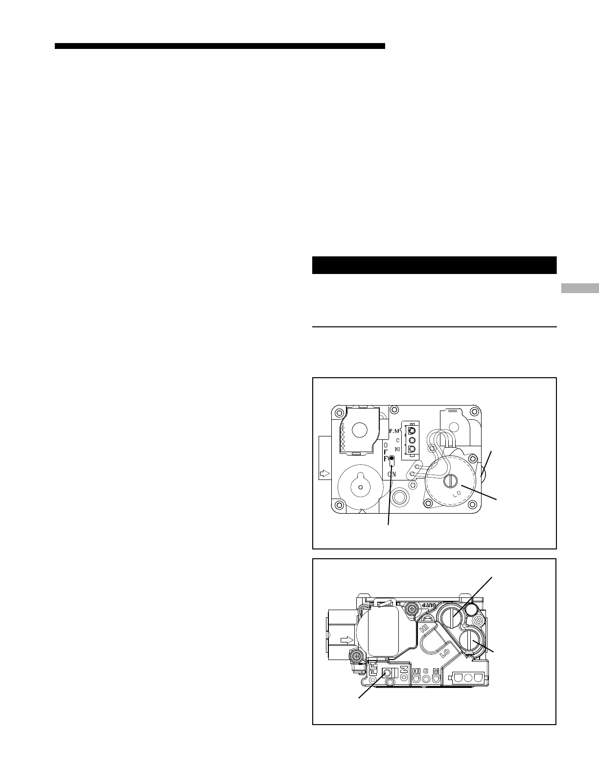
d. For the White-Rodgers gas valve model 36E:
1. Adjust low fire by removing the low adjustment
seal screw (See Figure 28).
2. To increase outlet pressure, turn the 3/32" socket
set screw clockwise.
To decrease outlet pressure, turn the set screw
counterclockwise.
Adjust regulator until pressure shown on mano-
meter matches the pressure specified in Table 9.
3. Replace low adjustment seal screw and tighten
securely.
4. Cycle the valve several times to verify regulator
setting.
5. Adjust high fire by removing the high adjustment
regulator cover screw (See Figure 28).
6. To increase outlet pressure, turn the regulator
adjust screw clockwise. To decrease outlet pressure,
turn the regulator adjust screw counterclockwise.
The final manifold pressure setting shall be as
specified in Table 9 with an input of no more than
nameplate rating and no less than 93% of the
nameplate rating, unless the unit is derated for
high altitude.
7. Replace high adjustment regulator cover screw and
tighten securely.
8. Cycle the valve several times to verify regulator
setting.
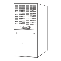
e. For the White-Rodgers gas valve model 36G:
1. Adjust low fire by removing the low adjustment
regulator cover screw (See Figure 29).
2. To increase outlet pressure, turn the regulator
adjust screw clockwise. To decrease outlet pressure,
turn the regulator adjust screw counterclockwise.
Adjust regulator until pressure shown on manom-
eter matches the pressure specified in Table 9.
3. Replace and tighten the regulator cover screw
securely.
4. Cycle the valve several times to verify regulator
setting.
5. Adjust high fire by removing the high adjustment
regulator cover screw (See Figure 29).
6. To increase outlet pressure, turn the regulator
adjust screw clockwise. To decrease outlet pressure,
turn the regulator adjust screw counterclockwise.
The final manifold pressure setting shall be as
specified in Table 9 with an input of no more than
nameplate rating and no less than 93% of the
nameplate rating, unless the unit is derated for
high altitude.
7. Replace high adjustment regulator cover screw and
tighten securely.
8. Cycle the valve several times to verify regulator
setting.
f. Turn off all electrical power to the system.
g. Remove the manometer and flexible tubing. Remove
the barbed fitting and replace the plug or tighten the
pressure test screw.
h. Turn on electrical power to the system and energize
valve.
i. Using a leak detection solution or soap suds, check for
leaks at plug or pressure boss screw.
CAUTION
!
Replace and/or tighten all plugs removed or loosened
when adjusting gas pressure. Leak check the fittings
before placing the furnace into regular service. Failure to
follow this warning could result in fire, explosion, or
property damage.
For LP gases, the final manifold pressure setting shall be
10.5" W.C. with an input of no more than the nameplate
rating and no less than 93% of the nameplate rating, unless
the unit is derated for altitude.
k
Gas Valve On / Off
Toggle Switch
1st Stage (LO)
Manifold
Pressure
Adjustment
2nd Stage (HI)
Manifold
Pressure
Adjustment
White-Rodgers 36E
White-Rodgers 36G
Gas Valve On / Off
Toggle Switch
1st Stage (LO)
Manifold
Pressure
Adjustment
2nd Stage (HI)
Manifold
Pressure
Adjustment
l