22 18-CD20D1-18
Installer’s Guide
CONTROL AND SAFETY SWITCH
ADJUSTMENT
LIMIT SWITCH CHECK OUT
The limit switch is a safety device designed to close the gas
valve should the furnace become overheated. Since proper
operation of this switch is important to the safety of the unit,
it must be checked out on initial start up by the
installer.
To check for proper operation of the limit switches, set the
thermostat to a temperature higher than the indicated
temperature to bring on the gas valve. Restrict the airflow
by blocking the return air or by disconnecting the blower.
When the furnace reaches the maximum outlet temperature
as shown on the rating plate, the burners must shut off. If
they do not shut off after a reasonable time and overheating
is evident, a faulty limit switch is probable and the limit
switch must be replaced. After checking the operation of the
limit control, be sure to remove the paper or cardboard from
the return air inlet, or reconnect the blower.
INDOOR BLOWER TIMING
Heating: The Integrated Furnace Control (IFC) controls the
variable speed indoor blower. The blower “on” time is fixed at
45 seconds after ignition. The FAN-OFF period is field
selectable by dip switches #1 and #2 located on the Inte-
grated Furnace Control between the 5-pin and 9-pin wire
connectors. The delay may be set at 60, 100, 140, or 180 sec-
onds. The factory setting is 100 seconds (See unit wiring
diagram).
Cooling: The fan delay-off period is set by dip switches on the
Integrated Furnace Control. The options for cooling delay off
is field selectable by dip switches #5 and #6.
The following table and graph explain the delay-off settings:
COOLING OFF - DELAY OPTIONS
SWITCH SETTINGS SELECTION
NOMINAL
AIRFLOW
5 - OFF 6 - OFF NONE SAME
5 - ON 6 - OFF 1.5 MINUTES 100% *
5 - OFF 6 - ON 3 MINUTES 50%
5 - ON 6 - ON ** 50 - 100%
WARNING
!
Disconnect power to the unit before removing the blower
door. Failure to follow this warning could result in property
damage, personal injury or death.
This unit is equipped with a blower door switch which cuts
power to the blower and gas valve causing shutdown when
the door is removed. Operation with the door removed or
ajar can permit the escape of dangerous fumes. All panels
must be securely closed at all times for safe operation of
the furnace.
NOTE:
Direct drive motors have bearings which are permanently
lubricated and under normal use, lubrication is not
recommended.
ROOM AIR THERMOSTAT
HEAT ANTICIPATOR ADJUSTMENT
Set the thermostat heat anticipator according to the current
flow measured, or the settings found in the notes on the
furnace wiring diagram (found inside the furnace casing).
INSTRUCTIONS TO THE OWNERS
In the event that electrical, fuel, or mechanical fail-
ures occur, the owner should immediately turn the gas
supply off at the manual gas valve, located in the
burner compartment (See Figure 27).
Also turn off electrical power to the furnace and
contact the service agency designated by your dealer.
WARNING
!
Should overheating occur, or the gas supply fail to shut off,
shut off the gas valve to the unit before shutting off the
electrical supply. Failure to follow this warning could result
in property damage, personal injury, or death.
OFF
50%
50%
80%
Dehumidify
Efficiency
Fast Cooling
1
minute
3
minutes
7.5
minutes
100% if necessary
OFF
See Wiring Diagram on the unit or in the Service Facts
for complete wiring setup for Enhanced Mode.
* - This setting is equivalent to BAY24X045 relay
benefit.
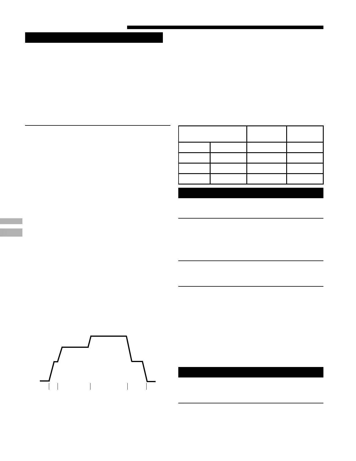
** - This selection provides ENHANCED MODE, which
is a ramping up and ramping down of the blower
speed to provide improved comfort, quietness,
and potential energy savings. See Wiring Diagram
notes on the unit or in the Service Facts for
complete wiring setup for ENHANCED MODE. The
graph which follows, shows the ramping process.
WARNING
!
EXPLOSION HAZARD!
PROPANE GAS IS HEAVIER THAN AIR AND MAY COL-
LECT IN ANY LOW AREAS OR CONFINED SPACES. IN
ADDITION, ODORANT FADE MAY MAKE THE GAS
UNDETECTABLE EXCEPT WITH A WARNING DEVICE. IF
THE GAS FURNACE IS INSTALLED IN A BASEMENT, AN
EXCAVATED AREA OR A CONFINED SPACE, IT IS
STRONGLY RECOMMENDED TO CONTACT A GAS
SUPPLIER TO INSTALL A GAS DETECTING WARNING
DEVICE IN CASE OF A GAS LEAK.
NOTE: The manufacturer of your furnace does NOT test any
detectors and makes no representations regarding any
brand or type of detector.
 Loading...