16
(4) Control Panel Identification
The following information explains the details of chiller
control. The details include hardware identification and
location, control strategies, limits and operating sequences.
Control Panel Location and
Internal Hardware
Component Description
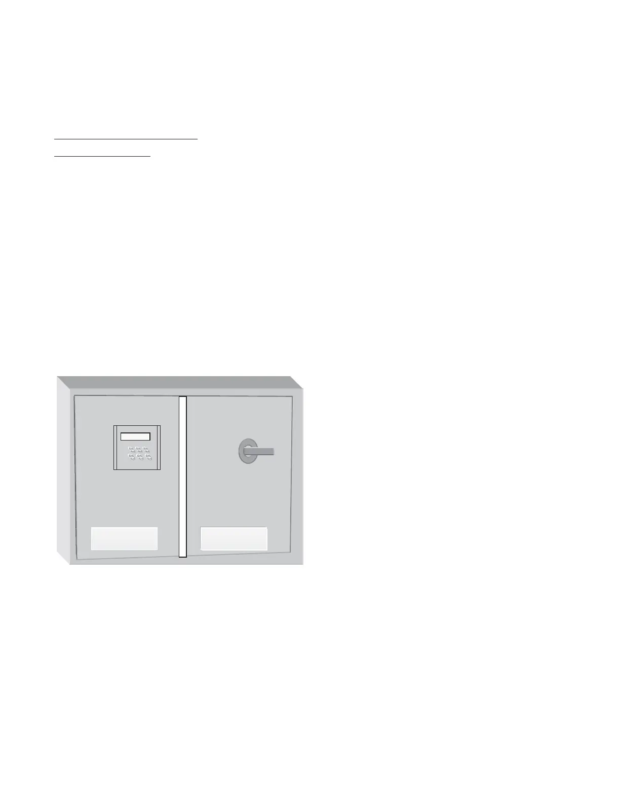
The main control panel (Figure 3) has two sections. The left
side (control side) includes clear language display
(mounted through door), chiller, circuit, purge, stepper, and
optional communications modules, a terminal block, and a
115Vac-control voltage to 24Vac transformer. The right side
(power side) consists of a main line voltage terminal block
or disconnect service for line power connections, line
voltage to control voltage transformer, relays, transformers,
starter module and purge module. Line voltage is restricted
to the right-hand side.
The inner control panel components are illustrated in
Figure 4. Modules are stacked in a top, bottom or middle
configuration.
Voltages in Panels
Voltages present within the unit control panel includes:
• Three phase line voltage (power side only)
• 115Vac control circuits
• 24Vac module power supply
Low voltage, low power (30Vdc or less — Class II) circuit
connection points are located on the left side of modules.
High voltage, high power (greater than 30Vdc — Class I)
circuit connection points are located on the right side of
modules. All 115Vac circuits are Class 1. See Figure 5.
The stepper drive uses less than 30Vdc however, the output
signals are Class 1 due to its output current (amps).
Class 1 and Class 2 wiring must not be routed together
without shielding.
Figure 3. Machine control panel
Control Side Power Side
 Loading...