RT-SVX36G-EN 51
Installation
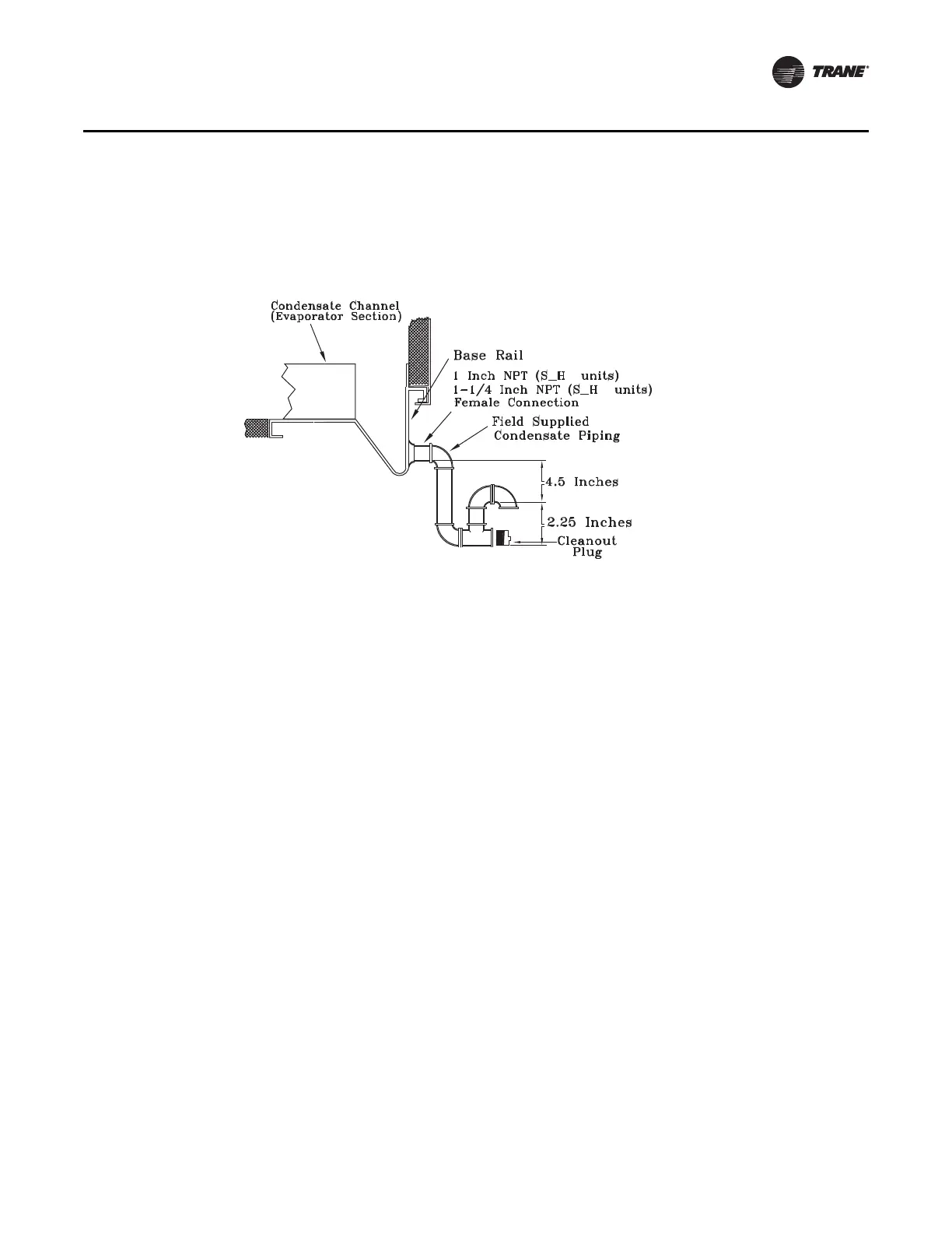
An additional 1-1/4” non-connectable water drain is located in the base rail within the heating
section.
Ensure that all condensate drain line installations comply with applicable building and waste
disposal codes.
Removing Supply and Exhaust/Return Fan Shipping Channels (Motors >5Hp)
Each supply fan assembly and exhaust fan assembly for S_HL units shipped with a motor larger
than 5 HP is equipped with rubber isolators (as standard) or optional spring isolators. Each return
fan assembly for S_HL units shipped with a motor larger than 5 HP is equipped with spring
isolators. Shipping channels are installed beneath each fan assembly and must be removed. To
locate and remove these channels, refer to Figure 20 and Figure 21, and use the following
procedures:
Rubber Isolators:
1. Remove and discard the shipping bolts from the fan assembly rails.
2. Elevate the fan-and-motor assembly and slide the shipping channels out from between the fan
assembly rails and the unit's base rail.
3. Lower the fan-and-motor assembly onto the isolators. Make sure that the pins at the top of the
isolators are engaged in the corresponding holes on the fan assembly.
4. Verify that the fan assembly is being supported by the isolators.
Spring Isolators:
See Figure 20 and Figure 21 for spring isolator locations.
1. Remove and discard the shipping tie down bolts.
2. Remove the shipping channels and discard.
Note: Fan assemblies not equipped with rubber or spring isolators have mounting bolts at the
same locations and must not be removed.
Note: If return fan backside spring isolator repair/replacement is required, access the backside of
the return fan by entering the unit filter section. Remove the top pivot bearings from the
three fixed- position return damper blades (bolted together as a single section with an angle
brace). Lift the three-blade section as a single unit from the return damper assembly and set
aside or lean in against the return fan frame. Then enter the return fan compartment from
the filter section to perform service work on the rear isolators.
Figure 19. Condensate Trap Installation
 Loading...


