SCXF-SVX01Q-EN
45
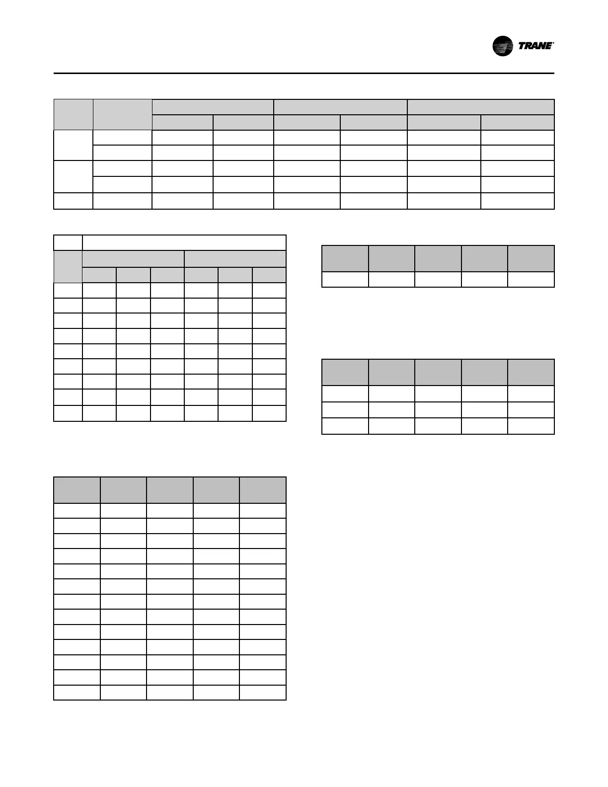
Table 27. Fan motor electrical data (continued)
HP TYPE
200V 460V 575V
FLA LRA FLA LRA FLA LRA
40
OPD 109.0 615.0 49.0 330.0 40.0 270.0
TEFC 111.0 758.0 47.4 320.0 38.0 280.0
50
ODP
N/A N/A
59.0 378.0 47.0 305.0
TEFC
N/A N/A
59.0 455.0 47.2 380.0
60 ODP
N/A N/A
71.0 464.0
N/A N/A
Table 28. VFD electrical data
VFD L.I.C.
HP
Without Bypass With Bypass
200V 460V 575V 200V 460V 575V
7.5 23.8 10.6 8.8 32.2 10.6 8.8
10 32.2 14 11.1 48.3 14 16.6
15 48.3 21 16.6 61.9 21 16.6
20 61.9 27.6 21.4 78.2 27.6 21.4
25 78.2 34 26.3 92 34 26.3
30 92 41 31.2 117 41 31.2
40 117 53 39.9 139.2 53 39.9
50 NA 64 50.6
n/a
64 50.6
60 NA 77 NA
n/a
77
n/a
Note: Values are at the maximum VFD input rating and not the
reduced motor values. L.I.C. = Line Input Current.
Table 29. Single stage electric heat electrical data
SXWF
Size
SXRF
Size Heat Kw
200V
Amps
460V
Amps
20 - 18 50 21.7
22 - 18 50 21.7
25 20 18 50 21.7
29 25 23 63.8 27.7
32 29 23 63.8 27.7
35 30 27 75 32.5
38 35 27 75 32.5
42 - 31.5 87.4 37.9
46 40 31.5 87.4 37.9
52 - 39 108.3 46.9
58 50 39 108.3 46.9
65 - 48 133.2 57.7
72 - 48 133.2 57.7
Table 29. Single stage electric heat electrical data
(continued)
SXWF
Size
SXRF
Size Heat Kw
200V
Amps
460V
Amps
80 60 48 133.2 57.7
Note: Electric heat amperage should not be considered when
determining minimum circuit ampacity. The current of the
unit in the heating mode will not exceed the current of the
unit in the cooling mode
Table 30. 2 stage electric heat electrical data
Unit Size
SCWF Heat kW
200V
Amps
460V
Amps
575V
Amps
90 76
N/A
95.39
N/A
100 76
N/A
95.39
N/A
110 76
N/A
95.39
N/A
Static Pressure Transducer
Installation (VAV units only)
Supply air static pressure controls the inverter option.
A static pressure head assembly ships separate in
control panel for field installation in the supply air duct
work. Installer is responsible for providing pneumatic
tubing.
Transducer Location
Place head assembly in an area of ductwork that will
provide an average and evenly distributed airflow
pattern. Use the following guidelines to determine an
appropriate installation location.
1. Locate static head assembly approximately 2/3 to 3/
4 the way down longest duct run, in an area
approximately 10 duct diameters downstream and
2 duct diameters upstream of major interferences,
turns, or changes in duct diameter.
2. When installing pneumatic tubing between head
assembly and transducer in control panel, do not
exceed 250ft for 1/4” OD tubing or 500ft for 3/8” OD
tubing.
IInnssttaallllaattiioonn -- EElleeccttrriiccaall
 Loading...


