16
PTAC-SVX004A-EN
System Configuration
Adjusting Air Direction- Only for
Duct Installations
1. Remove front panel.
Louver screws
Louver screws
2. Remove louver screws that hold the louver insert in
place on the back side of the front panel.
3. Turn louver insert and rotate it 180°.
4. Replace louver insert.
5. Replace screws and the front panel.
DIP Switches
WWAARRNNIINNGG
HHaazzaarrddoouuss VVoollttaaggee!!
FFaaiilluurree ttoo ddiissccoonnnneecctt ppoowweerr bbeeffoorree sseerrvviicciinngg ccoouulldd
rreessuulltt iinn ddeeaatthh oorr sseerriioouuss iinnjjuurryy..
DDiissccoonnnneecctt aallll eelleeccttrriicc ppoowweerr,, iinncclluuddiinngg rreemmoottee
ddiissccoonnnneeccttss bbeeffoorree sseerrvviicciinngg.. FFoollllooww pprrooppeerr
lloocckkoouutt//ttaaggoouutt pprroocceedduurreess ttoo eennssuurree tthhee ppoowweerr
ccaann nnoott bbee iinnaaddvveerrtteennttllyy eenneerrggiizzeedd.. VVeerriiffyy tthhaatt nnoo
ppoowweerr iiss pprreesseenntt wwiitthh aa vvoollttmmeetteerr..
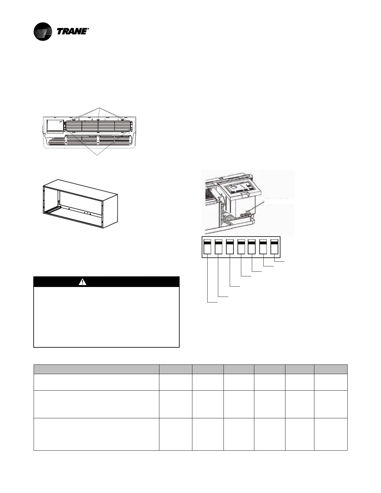
The auxiliary DIP switch controls are located behind the
front panel and through an opening below the control
panel. To access, you must remove the front panel. The
DIP switches are accessible without opening the
control box.
IImmppoorrttaanntt:: Electrical power supply must be
disconnected from unit to apply DIP switch
changes.
NNoottee:: Factory settings for DIP switches will be in the
DOWN position. Refer to the following for the
functionality of each DIP switch position.
Figure 1. DIP switch/wall thermostat enable
1 2 3 4 5 6 7
Freeze Guard
Setpoint Limit 2
Setpoint Limit 1
Wal
l Thermostat Enable
Elec
tric Heat Only
for Heat Pumps
Fan CON/CYC for Cooling/
Energy Saver: Cooling
Fan CON/CYC for Heating
Energy Saver: Heating
Table 5. DIP Switch Descriptions
DIP Switch Number Up Down
Default Remarks
1: Electric Heating Only/Emergency Heat. This
setting is typically used for Emergency Heating.
Electric
Heat Only
Heat Pump Down For only
heat pump
units.
2: Wall Thermostat Enable. A wired wall thermostat
can be connected to the unit. The DIP switch must be
adjusted accordingly in order to allow the wall
thermostat control of the unit. When unit is in wall
thermostat mode, the control panel is disabled.
Wall
Thermostat
Enable
Control
Panel
Enable
Down
3: Energy Saver DIP Switches. Allows the fan to
operate in continuous or cycle mode while the unit is in
heating or cooling mode. DIP Switch 3: Continuous and
allows the fan to run continuously, circulating air even
when the temperature setting has been satisfied. DIP
Switch.
Fan
Continuous
Run for
Heating.
Fan Cycle
for Heat
Down
 Loading...