RLC-SVX14H-GB
71
This section contains an overview of the operation of
RTWD/RTUD chillers equipped with microcomputer-
based control systems. It describes the overall operating
principles of the RTWD/RTUD water chiller.
Note: To ensure proper diagnosis and repair, contact a
qualifi ed service organization if a problem should occur.
General - RTWD
The Model RTWD units are dual-compressor, dual
circuit, water-cooled liquid chillers.
These units are equipped with unit-mounted starter/
control panels.
The basic components of an RTWD unit are:
• Unit-mounted panel containing starter and Tracer
CH530 controller and Input/Output LLIDS
• Helical-rotary compressor
• Evaporator
• Electronic expansion valve
• Water-cooled condenser with integral subcooler
• Oil supply system
• Oil cooler (application dependent)
• Related interconnecting piping
• AFD (Adaptive Frequency Drive) on HSE versions
Components of a typical RTWD/RTUD unit are identifi ed
in the following diagram.
General - RTUD
The Model RTUD units are dual compressor, dual circuit
compressor chillers.
These units are equipped with unit mounted starter/
control panel.
The basic components of an RTUD unit are:
• Unit-mounted panel containing starter and tracer
CH530 controller and Input/Output LLIDs
• Helical-rotary compressor
• Evaporator
• Electronic expansion valve
• Oil supply system
• Oil cooler
• Related interconnecting piping
Components of a typical RTUD unit are identifi ed in the
following diagram.
WARNING Contains Refrigerant!
System contains oil and refrigerant under high pressure.
Recover refrigerant to relieve pressure before opening the
system. See unit nameplate for refrigerant type. Do not
use non-approved refrigerants, refrigerant substitutes, or
refrigerant additives. Failure to follow proper procedures
or the use of non-approved refrigerants, refrigerant
substitutes, or refrigerant additives could result in death
or serious injury or equipment damage.
WARNING Hazardous Voltage!
Disconnect all electric power, including remote
disconnects before servicing. Follow proper lockout/
tagout procedures to ensure the power can not be
inadvertently energized. Failure to disconnect power
before servicing could result in death or serious injury.
RTWD HSE version
• Time before to work on the electrical panel of the unit:
once the AFD is off (confi rmed by the extinction of the
display), it is mandatory to wait one minute before
working on the electrical panel.
• However, for any intervention in the AFD, the
indicated time on the label of the AFD must be
respected.
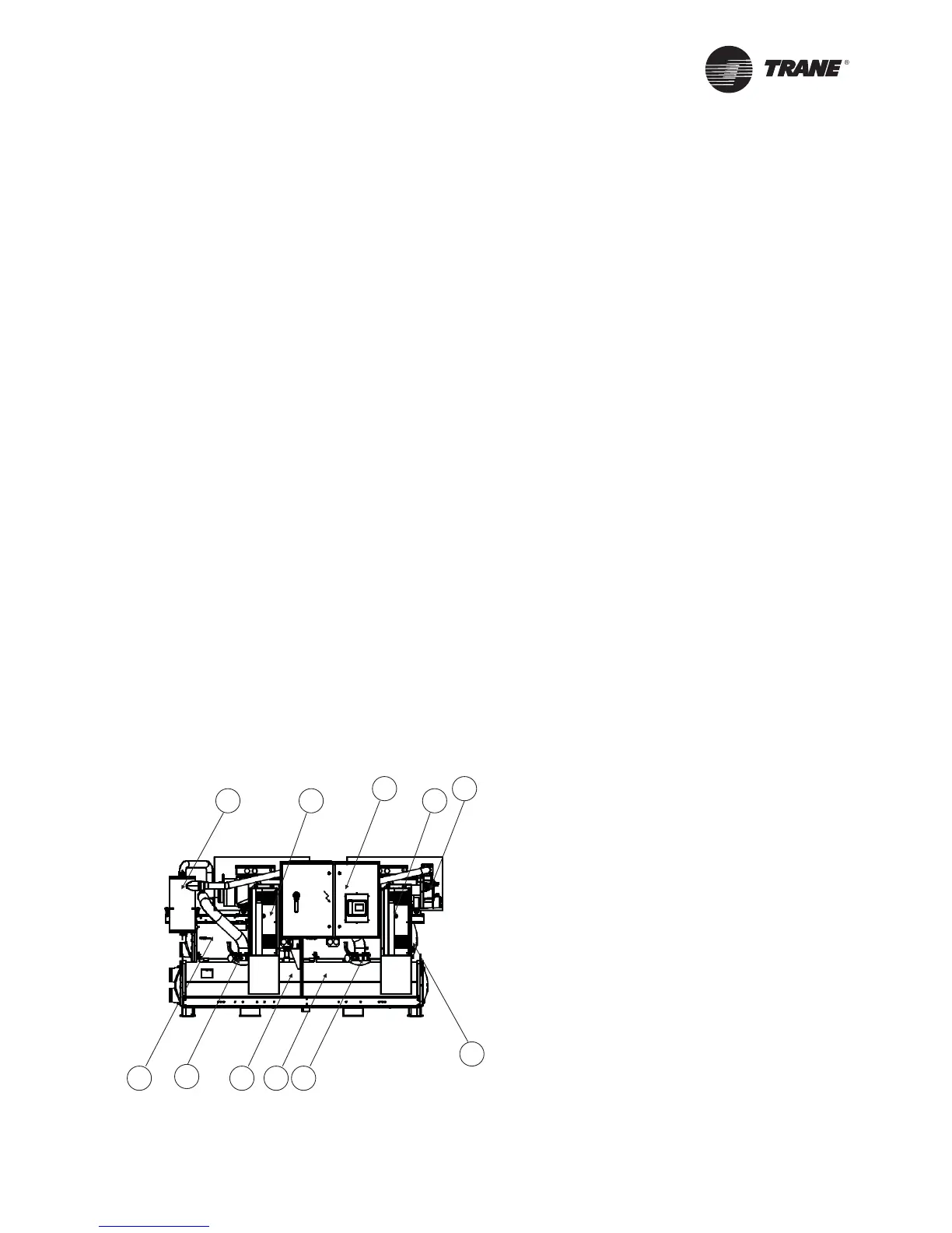
Operating Principles
A
B C
D
E
E
FGH
I J
A = Oil separator circuit 1
B = Control panel
C = Compressor circuit 2
D = Condenser circuit 2 (RTWD only)
E = Suction service valve
F = Evaporator circuit 2
G = Evaporator circuit 1
H = Condenser circuit 1 (RTWD only)
I = Adaptive Frequency Drive circuit 1
J = Adaptive Frequency Drive circuit 2
Figure 13 - Components (front view)
 Loading...


