RTWB-SVN01B-E4
12
Installation Mechanical
Flow
switch
Balance valve
Air vent
Stop valves
Thermometers
Expansion joints
Stop valves
Evaporator
Filter
Drainage
Manometer
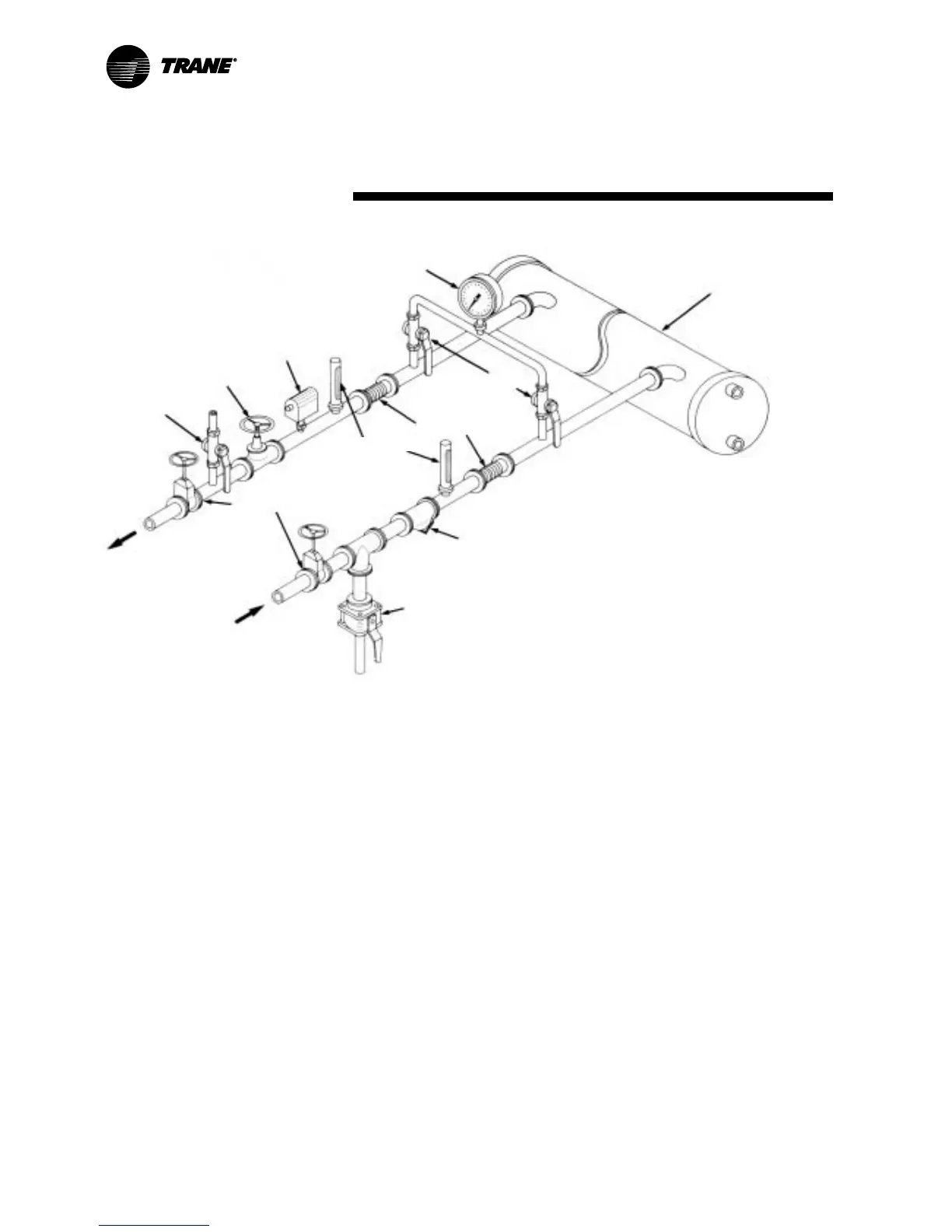
Figure 7 – Suggested piping for typical RTWB evaporator
Evaporator piping
components
“Piping components“ include all
devices and controls used to provide
proper water-system operation and
unit operating safety.
These components and their general
location are given above:
Entering chilled-water piping
•
Air vents (to bleed air from system)
•
Water pressure gauges with shutoff
valves
•
Vibration eliminators
•
Shutoff (isolation) valves
•
Thermometers (if desired)
•
Cleanout tees
•
Pipe strainer
To prevent tube damage, install a
strainer in the water inlet piping of
the evaporator.
Leaving chilled-water piping
•
Air vents ( to bleed air from
system).
•
Water pressure gauges with shutoff
valves.
•
Vibration eliminators.
•
Shutoff (isolation) valves.
•
Thermometers.
•
Cleanout tees.
•
Balancing valve.
•
Flow switch
•
Pressure-relief valve.
 Loading...