40
S8V2-SVX001-1A-EN
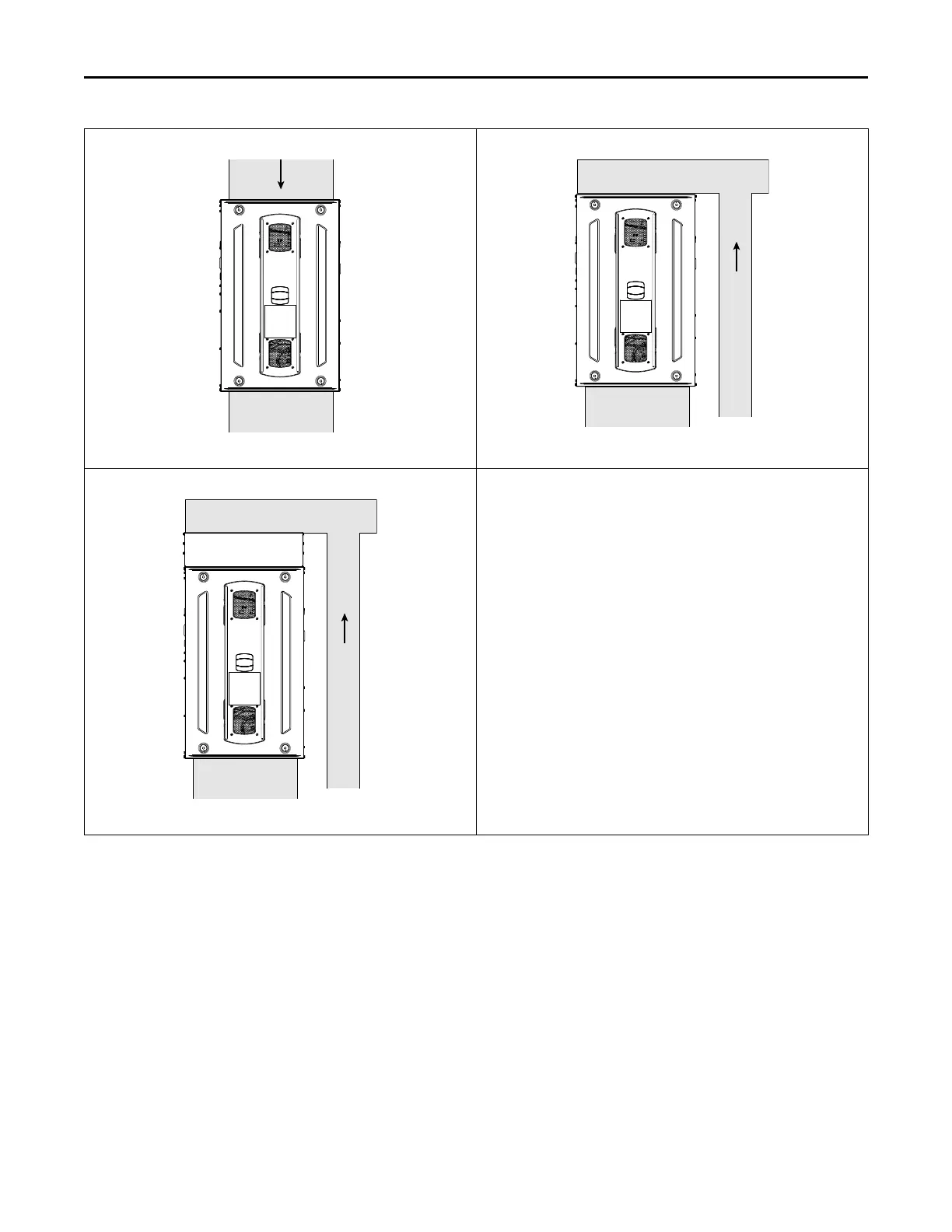
Downflow Furnace with Top Return
Refer to Step 13., Step 14., Step 17., and Step 8.
Downflow Furnace with Top Return and Plenum
Refer to Step 13., Step 15., Step 17., and Step 8.
Downflow Furnace with Top Return and Plenum with Filter Box
Refer to Step 13., Step 16., Step 14., and Step 8.
IInnssttaallllaattiioonn IInnssttrruuccttiioonnss
1. Remove the bottom plate.
2. Create ducting and set the furnace in place.
3. Match the filter cabinet flush to the back and
bottom sides of the furnace cabinet and secure in
place with screws.
4. Mark the two areas to be cut out for the return air.
5. Cut out the two sections of the cabinet and BAYLIFT
kit to be removed.
6. Attach ducting to the filter box.
7. The ducted pedestal will use ducted air from a
remote location.
8. Seal per local codes and requirements.
9. Using guides, remove the cutout for the side return.
10. Create ducting and set the furnace in place. Use
screws to attach ducting to the furnace cabinet.
11. Seal bottom panel per local codes and
requirements.
12. Seal all other panels per local codes and
requirements.
13. Remove the top plate.
14. Attach the ducting to the top of the furnace.
15. Attach the plenum ducting to the top of the furnace.
16. Attach the filter box to the top of the furnace.
17. Install remote filter.
FFuurrnnaaccee GGeenneerraall IInnssttaallllaattiioonn
 Loading...