58
18-CE04D1-1B-EN
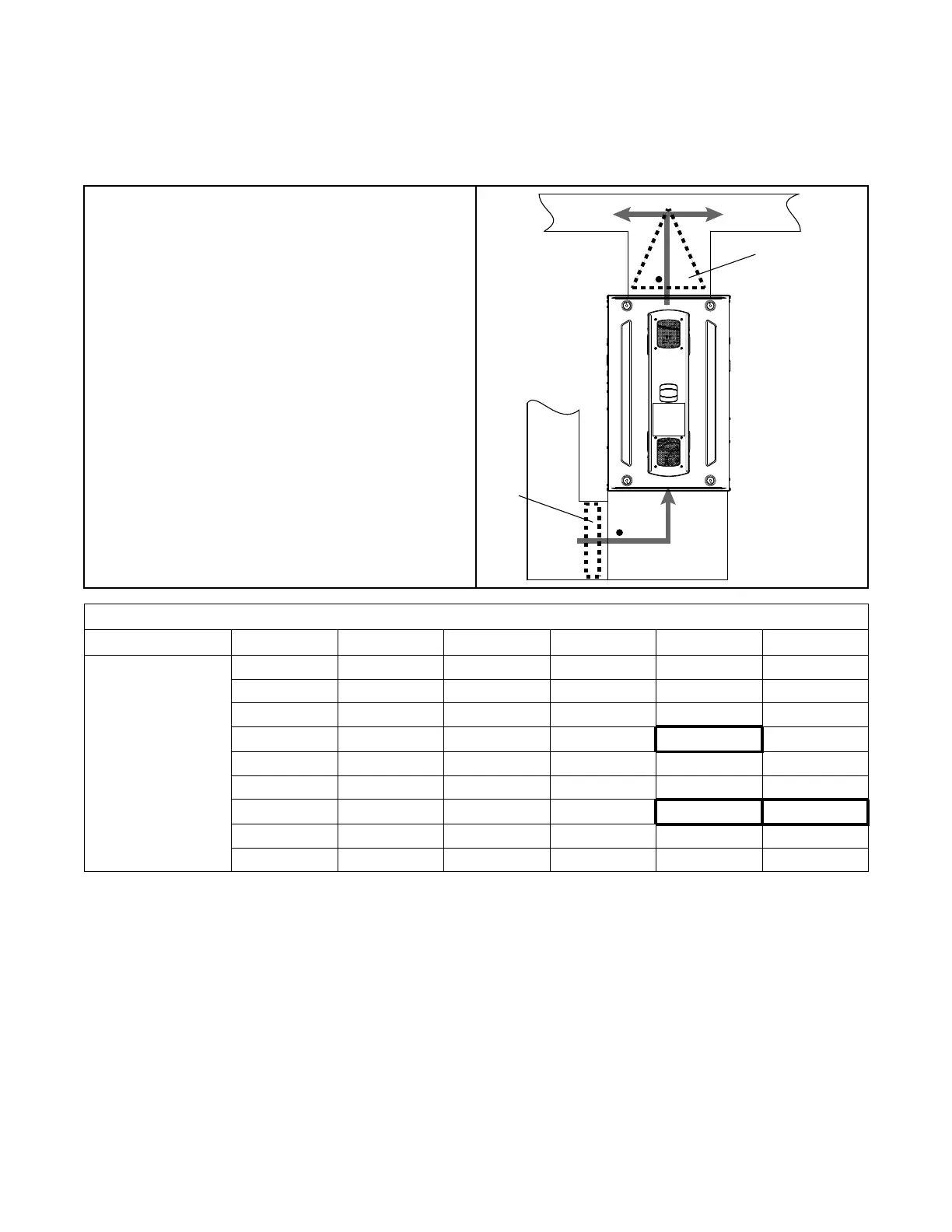
Setting Airflow
With all ductwork connected and a clean filter in place, measure the
External Static Pressure (ESP) of the unit in locations below. Use the
appropriate airflow table for the furnace and outdoor unit installed.
Measurements must be made prior to the evaporator coil, if equipped,
and after the filter.
Evaporato
r
Coil
Clean
Filter
Furnace Airflow (CFM) Vs. External Static Pressure (in. W.C.)
Model
Tap
0.1 0.3 0.5 0.7 0.9
S8X1B080M4PSAA
S8X2B080M4PSAA
1 633 297 — — —
2 957 800 719 428 213
3 1220 1080 940 800 660
4 1403 1298 1192
1087
(a)
981
5 1524 1428 1336 1248 1164
6 1684 1574 1544 1401 1337
7 1700 1625 1551
1476
(b)
1401
(c)
8 1858 1790 1723 1656 1589
9 1967 1898 1829 1760 1691
(a)
Exapmple 1, 2
(b)
Example 1
(c)
Example 2
Example 1: S8X2B080M4PSAAA (Default Tap 7)
Cooling / HP
• 3 Ton Single Stage Outdoor
• Total ESP = 0.7” W.C.
• Required Airflow = 1050 cfm (3T x 350 cfm/ton)
• New Tap Number = Tap 4
Example 2: S8X2B080M4PSAA (Default Tap 3 & 7)
• 4 Ton Two Stage Outdoor
• Total 2
nd
Stage ESP = 0.9” W.C.
• Total 1
st
Stage ESP = 0.6” W.C.
• Required 2
nd
Stage Airflow = 1400 cfm (4T x 350
cfm/ton)
• Required 1
st
Stage Airflow = 1050 cfm (2
nd
stage
airflow x .75)
• New 2
nd
Stage Tap Number = Tap 7 (no change)
• New 1
st
Stage Tap Number = Tap 4
 Loading...