38
S9V2-VS-SVX001-1C-EN
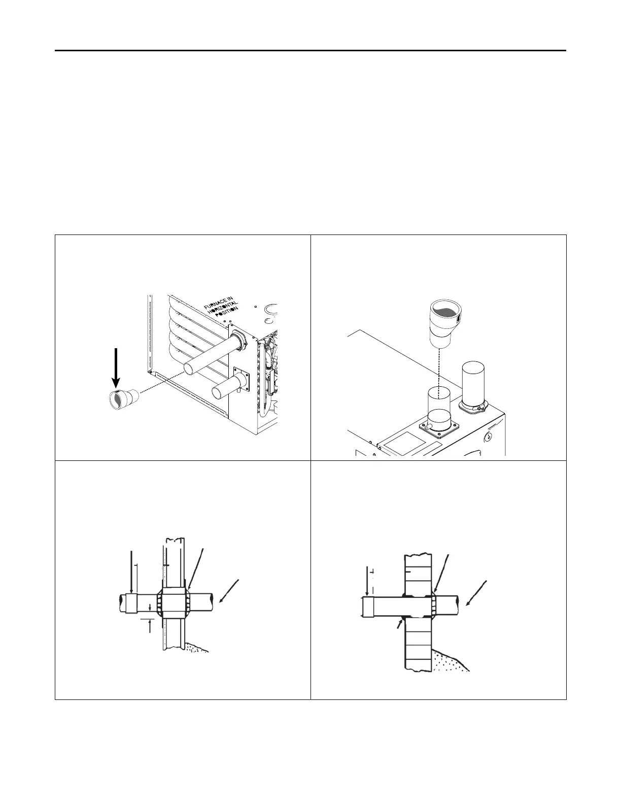
Horizontal Venting
Note: Insure that vent piping is sloped 1/4" per foot and that piping is supported properly to prevent sags and condensate pooling.
3” Venting requirements
Important: To determine if your application requires 3” venting, see the Maximum Vent Length Table.
Important: Horizontal venting application must use the 2” x 3” offset reducing coupling. Vertical venting applications do not require the
reducing coupling to be offset.
When the vent pipe is exposed to temperatures below freezing, e.g., when it passes through unheated spaces, etc., the pipe
must be insulated with 1/2 inch (12.7 mm) thick Armaflex-type insulation or equal.
If the space is heated sufficiently to prevent freezing, then the insulation will not be required. If domestic water pipes are not
protected from freezing then the space meets the condition of a heated space.
Note: If your furnace comes with a factory supplied 2" X 3" offset
reducing coupling it is used for 3" vent pipe installation. Make
sure the marking "TOP" is located on the top side of the pipe in
horizontal venting applications. The straight side of the
coupling must be on bottom for proper drainage of condensate.
Note: For Canadian applications, BAYREDUCE 2” x 3” offset reducing
coupling meets ULC-S636 requirements. Make sure the
marking "TOP" is located on the top side of the pipe. The
straight side of the coupling must be on bottom for proper
drainage of condensate in horizontal venting.
LABEL
SAYS
“TOP”
2" TO 3" COUPLING
CPL01544
BAYREDUCE may be
used in Canadian
applications to meet
ULC-S636
CPL01544 IS FACTORY
SUPPLIED ONLY WITH THE
120,000 BTUH FURNACE
MODELS
2" TO 3" COUPLING
CPL01544 IS FACTORY
SUPPLIED ONLY WITH THE
120,000 BTUH FURNACE
MODELS
CPL01544
BAYREDUCE may be
used in Canadian
applications to meet
ULC-S636
COMBUSTIBLE MATERIAL WALL
A minimum clearance of 1" to combustible materials must be
maintained when using single wall stainless steel venting.
Shield material to be a minimum of 24 gauge stainless or aluminized
sheet metal. Minimum dimensions are 12"x12". Shield must be
fastened to both inside and outside of wall. Use screws or anchor type
fasteners suited to the outside or inside wall surfaces.
NONCOMBUSTIBLE MATERIAL WALL
The hole through the wall must be large enough to maintain pitch of
vent and properly seal.
Use cement mortar seal on inside and outside of wall.
COUPLING
(PLASTIC
VENTING)
STUD
PVC WALL
MOUNT FLANGE
(OPTIONAL)
APPROVED
TERMINATION
1” CLEARANCE
(AIR SPACE)
VENTING THROUGH COMBUSTIBLE WALLS
Pitch - 1/4 Inch Per Foot
CLEARANCE (0” ACCEPTABLE FOR PVC VENT PIPE)
(1” ACCEPTABLE FOR TYPE 29-4C STAINLESS STEEL VENT PIPE)
12” MINIMUM ABOVE
NORMALLY EXPECTED
SNOW ACCUMULATION
LEVEL
6 IN. MIN.
(TO JOINT)
COUPLING
(PLASTIC
VENTING)
PVC WALL
MOUNT FLANGE
(OPTIONAL)
APPROVED
TERMINATION
CEMENT
MORTAR SEAL
INSIDE &
OUTSIDE
VENTING THROUGH NON-COMBUSTIBLE WALLS
Pitch - 1/4 Inch Per Foot
12” MINIMUM ABOVE
NORMALLY EXPECTED
SNOW ACCUMULATION
LEVEL
6 IN. MIN.
(TO JOINT
)
FFuurrnnaaccee GGeenneerraall IInnssttaallllaattiioonn
 Loading...


