TAM78
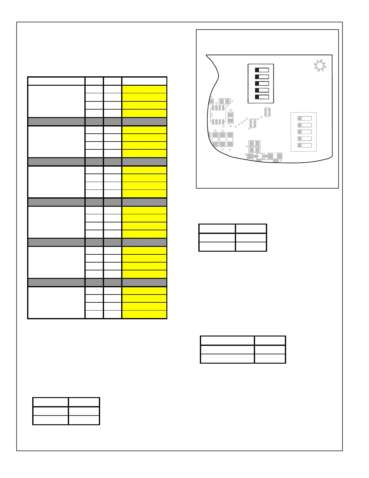
Dip Switch S1
• Set the S1-1 and S1-2 dip switches for the OD
multiplier (tonnage) per the chart.
NOTE: All dip switches are factory set to “OFF”.
INDOORMODEL S1‐1 S1‐2 ODMULTIPLIER
OFF OFF 2
OFF ON 1.5
ON OFF 2.5
ON ON 3
OFF OFF 2
OFF ON 1.5
ON OFF 2.5
ON ON 3
OFF OFF 3
OFF ON 2
ON OFF 2.5
ON ON 3.5
OFF OFF 3.5
OFF ON 2.5
ON OFF 3
ON ON 4
OFF OFF 4
OFF ON 3
ON OFF 3.5
ON ON 4.5**
OFF OFF 4.5**
OFF ON 3.5
ON OFF 4
ON ON 5
*Maybe"A"or"T"
**NotanactualODsize
NOTE:TheODmultiplierinconjuctionwiththe
CFM/TONcanbeusedtoadjusttotalairflowforyour
application.
Example:4.5Tx370CFM/TON=1665CFM
*AM7A0C42H31SA
*AM7A0C48H41SA
*AM7A0C60H51SA
*AM7A0A24H21SA
*AM7A0B30H21SA
*AM7A0C36H31SA
• Set the S1-3 dip switch for AC or HP.
ODTYPE S1‐3
HP OFF
AC ON
S1
Airflow Control (AFC)
1
1
12345
12345
HP
2(Compressor)
2(Stages)
AC (System)
}
OUTDOOR
Capacity (Tons)
OUTDOOR
}
Torque
CFM/Ton
Cool OffDelay
}
INDOOR
CFM
+12V
R13
R14
R1
R4
1
U1
RNET 1
S1
on
on
S2
RNET 2
R
6
C22
C19
C
15
C
12
C18
C21
C10
D9
L1
R22
• Set the S1-4 dip switch for the number of stages
on the outdoor unit.
ODSTAGES S1‐4
1 OFF
2 ON
• Set the S1-5 dip switch for the number of
compressors.
#COMPRESSORS S1‐5
1 OFF
2 ON
16 SEER = 1 Compressor
19 SEER = 2 Compressors
20 SEER = 2 Compressors
16 SEER = 2 Stages
19 SEER = 2 Stages
20 SEER = 2 Stages
• Note: This dip switch should be changed while the
power is off or no demand is present. The power
must be shut off and then re-applied in order for the
AFC to recognize the change.
 Loading...