32 CNT-SVX11A-EN
Troubleshooting
Important! When viewing the Tracer
ZN524 through the Rover service
tool, it is important that the
version be up-to-date. To help
ensure that your version is the
most recent, contact you local
Trane sales representative or
service center.
WARNING
Live Electrical Components
During installation, testing, servicing
and troubleshooting of this product, it
may be necessary to work with live
electrical components. Have a qualified
licensed electrician or other individual
who has been properly trained in han-
dling live electrical components per-
form these tasks. Failure to follow all
electrical safety precautions when
exposed to live electrical components
could result in death or serious injury.
Led Operation
Table 15:
Red Service LED
Black Service Push Button
Note: If the Service push button is
held down for more than 15
seconds, the Tracer ZN524 Unit
Controller will uninstall itself from
the ICS communication network
and shut down all unit operation.
This mode is indicated by the red
Service LED flashing once every
second. See the Red Service LED
section. Use Rover service tool to
restore the unit to normal
operation.
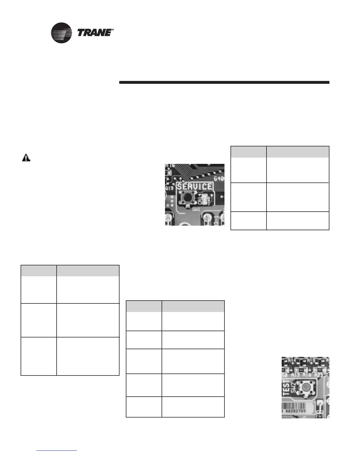
The Service
push button,
located at the
bottom center
of the con-
troller, can be
used to install
the Tracer
ZN524 Unit
Controller in a
communication
network. Refer
to the Rover
and Tracer Summit product literature
for more information.
Green Status LED
The green LED normally indicates
whether or not the controller is pow-
ered on (24 VAC).
Table 16:
Green status LED activity
Yellow Comm LED
The yellow Comm LED blinks at the
rate the controller receives communica-
tion. The yellow LED does not blink
when the controller is transmitting
communication data.
Table 17:
Yellow comm LED activity
Manual Output Test
The test sequence verifies output and
end device operation. The manual out-
put test can be conducted to verify out-
put wiring and actuator operation, with-
out using the Rover service tool, by
pressing the test button.
Many service calls are initiated due to
unit diagnostics, so the test sequence
attempts to clear unit diagnostics and
restore normal unit operation prior to
testing the outputs. If the diagnostics
remain after an attempt to clear diag-
nostics, the status LED lights in a two-
blink pattern, indicating the diagnostic
condition is still present.
See Table 18,
Page 33 for more
details.
Yellow LED Description
activity
LED off Controller is not detecting
continuously. any communication.
(Normal for standalone
applications.)
LED blinks or . The controller detects
flickers communication. (Normal
for communicating
applications, including
data sharing.)
LED on Abnormal condition or
continuously. extremely high traffic on
the link.
Red LED Description
activity
LED is off
continuously
after power is Normal operation.
applied to the
controller.
LED is on
continuously, Someone is pressing
even when the Service push button
power is first or the controller has
applied to the failed.
controller.
Un-install (normal
controller mode). Use
LED flashes Rover service tool to
about once restore the unit to normal
every second. operation. Refer to the
Rover product literature
for more information.
Green LED Description
activity
LED is on Power on
continuously. (normal operation).
LED blinks The controller is in
(1 blink per manual output test mode.
second) No diagnostics present.
The controller is in manual
LED blinks output test mode.
(2 blinks One or more diagnostics
per second). are present.
LED blinks Wink mode
1/4 second on,
1/4 second off
for 10 seconds
Power is off.
LED off Controller failure.
Test button is pressed.
Figure 19:
Blue
test button
Figure 18:
Black service button

 Loading...


