20 18-CD19D5-10
Installer’s Guide
▲
WARNING
!
FIRE OR EXPLOSION HAZARD
Failure to follow the safety warnings exactly could result in
serious injury, death or property damage.
Never test for gas leaks with an open flame. Use a commer-
cially available soap solution made specifically for the detec-
tion of leaks to check all connections. A fire or explosion may
result causing property damage, personal injury, or loss of life.
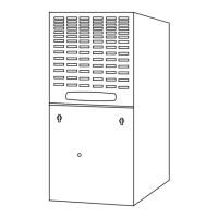
GAS PIPING
The upflow/horizontal furnace is shipped standard for left side
installation of gas piping. A knockout is provided on the right
side for an alternate gas piping arrangement. See Figures 29-31
on page 21.
The installation of piping shall be in accordance with piping
codes and the regulations of the local gas company. Pipe joint
compound must be resistant to the chemical reaction with
liquefied petroleum gases.
Refer to piping Table 8, for delivery sizes. Connect gas supply to
the unit, using a ground joint union and a manual shut-off valve
as shown in Figures 29-31. National codes require a condensa-
tion drip leg to be installed ahead of the controls as shown in
Figures 29-31.
The furnace and its individual shut-off valve must be disconnected
from the gas supply piping system during any pressure testing of
that system at test pressures in excess of 1/2 psig (3.5 kPa).
The furnace must be isolated from the gas supply piping by
closing its individual manual shut-off valve during any pressure
testing of the gas supply piping system at test pressures equal to
or less than 1/2 psig (3.5 kPa).
NOTE:
Maximum pressure to the gas valve for natural gas is 13.8"
W.C. Minimum pressure is 5.0" W.C. Maximum pressure to
the gas valve for propane is 13.8" W.C. Minimum pressure is
11.0" W.C.
All gas fittings must be checked for leaks using a soapy
solution before lighting the furnace.
DO NOT CHECK WITH AN
OPEN FLAME!
TABLE 8
NATURAL GAS ONLY
TABLE OF CUBIC FEET PER HOUR OF GAS
FOR VARIOUS PIPE SIZES AND LENGTHS
PIPE
SIZE
LENGTH OF PIPE
10 20 30 40 50 60 70
1/2 132 92 73 63 56 50 46
3/4 278 190 152 130 115 105 96
1 520 350 285 245 215 195 180
1-1/4 1050 730 590 520 440 400 370
This table is based on pressure drop of 0.3 inch W.C. and 0.6 SP.GR. gas
TABLE 9
ORIFICE SIZES
INPUT
RATING
BTUH
NUMBER
OF
BURNERS
MAIN BURNER ORIFICE
DRILL SIZE
NAT. GAS LP GAS
40,000
60,000
80,000
100,000
120,000
2
3
4
5
6
45
45
45
45
45
56
56
56
56
56
COMBUSTION AND INPUT CHECK
1. Make sure all gas appliances are off except the furnace.
2. Clock the gas meter with the furnace operating (determine
the dial rating of the meter) for one revolution.
3. Match the “Sec” column in the gas flow (in cfh) Table 10
with the time clocked.
4. Read the “Flow” column opposite the number of seconds clocked.
5. Use the following factors
if necessary:
For 1 Cu. Ft. Dial Gas Flow CFH = Chart Flow Reading ÷2
For 1/2 Cu Ft. Dial Gas Flow CFH = Chart Flow Reading ÷4
For 5 Cu. Ft. Dial Gas Flow CFH =
10X Chart Flow Reading ÷4
6. Multiply the final figure by the heating value of the gas ob-
tained from the utility company and compare to the name-
plate rating. This must not exceed the nameplate rating.
7. Changes can be made by adjusting the manifold pressure or
changing orifices (orifice change may not always be re-
quired). To adjust the manifold pressure:
a. Turn off all electrical power to the system.
b. Attach a manifold pressure gauge to the outlet pressure
tap marked “OUT PRESS TAP” on White-Rodgers gas
valve model 36F or boss marked “OUT P” on
White-Rodgers gas valve model 36G. (See Figure 33 for
White-Rodgers gas valve model 36F and Figure 32 for
White-Rodgers gas valve model 36G.). For the gas valve
model 36F, measurement requires removal of the plug
and installation of a barbed fitting. Attach flexible tubing
and a manometer to the barbed fitting. For the gas valve
model 36G, do not remove the pressure tap test screw.
Loosen the pressure tap test screw one turn and install
5/16" flexible tubing and a manometer directly onto the
outlet pressure boss.
c. Turn on system power and energize valve.
d. Remove the regulator adjustment screw cap on the gas
valve for manifold pressure adjustment.
e. Turn the adjustment nut clockwise to increase the gas
flow rate, and counterclockwise to decrease the gas flow
rate using a 3/32" hex wench.
f. The final manifold pressure setting shall be 3.5" W.C.
with an input of no more than nameplate rating and no
less than 93% of the nameplate rating, unless the unit is
derated for high altitude.
g. Replace the regulator adjustment screw cap and tighten
securely.
h. Turn off all electrical power to the system.
i. Remove the manometer and flexible tubing. Remove the
barbed fitting and replace the plug or tighten the
pressure test screw.
j. Turn on electrical power to the system and energize
valve.
k. Using a leak detection solution or soap suds, check for
leaks at plug or pressure boss screw.
▲
CAUTION
!
Replace and/or tighten all plugs removed or loosened when
adjusting gas pressure. Leak check the fittings before placing
the furnace into regular service. Failure to follow this warning
could result in fire, explosion, or property damage.
Table 9 lists the main burner orifices used with the furnace. If a
change of orifices is required to correct the furnace input rating
refer to Table 12.
 Loading...