22 18-CD19D5-10
Installer’s Guide
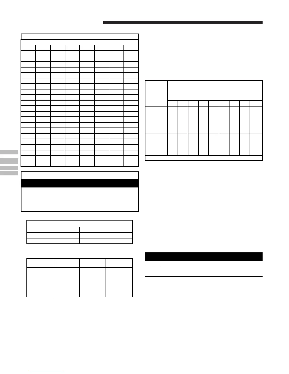
If the desired input rate cannot be achieved with a change in
manifold pressure, then the orifices must be changed. LP
installations will require an orifice change. See Table 13 for help
in selecting orifices if orifice change is required. Furnace input
rate and temperature rise should be checked again after chang-
ing orifices to confirm the proper rate for the altitude.
Installations above 4,000 feet may require a pressure switch
change. If required, use the BAYHALT*** Kit (High Altitude
Accessory Kit) listed in PRODUCT DATA.
TABLE 13
Orifice
Twist Drill
Size If
Installed
At Sea
Level
ALTITUDE ABOVE SEA LEVEL
and Orifice Required At Other Elevations
2000 3000 4000 5000 6000 7000 8000 9000 10000
42
43
44
45
46
47
42
44
45
46
47
48
43
44
45
47
47
48
43
44
45
47
47
49
43
45
46
47
48
49
44
45
47
48
48
49
44
46
47
48
49
50
45
47
48
49
49
50
46
47
48
49
50
51
47
48
50
50
51
52
54
55
56
57
58
54
55
56
58
59
55
55
56
59
60
55
55
57
59
60
55
56
57
60
61
55
56
57
60
62
55
56
58
61
62
56
56
59
62
63
56
56
59
63
63
56
57
60
63
64
From National Fuel Gas Code - Table F-4
START-UP AND ADJUSTMENT
PRELIMINARY INSPECTIONS
With gas and electrical power “OFF”
1. Duct connections are properly sealed
2. Filters are in place
3. Venting is properly assembled
4. Blower door is in place
Flip the switch on the main gas valve within the unit to the
“OFF” position. Turn the external gas valve to “ON”. Purge the
air from the gas lines. After purging, check all gas connections
for leaks with a soapy solution — DO NOT CHECK WITH AN
OPEN FLAME. Allow 5 minutes for any gas that might have
escaped to dissipate. LP Gas being heavier than air may require
forced ventilation. Flip the switch on the gas valve in the unit to
the “ON” position.
LIGHTING INSTRUCTIONS
▲
WARNING
!
DO NOT attempt to manually light the burner. Failure to follow
this warning could result in property damage, personal injury,
or death.
Lighting instructions appear on each unit. Each installation
must be checked out at the time of initial start up to insure
proper operation of all components. Check out should include
putting the unit through one complete cycle as outlined below.
Turn on the main electrical supply and set the thermostat above
the indicated temperature. The ignitor will automatically heat,
then the gas valve is energized to permit the flow of gas to the
burners. After ignition and flame is established, the flame
control module monitors the flame and supplies power to the gas
valve until the thermostat is satisfied.
TABLE 10
GAS FLOW IN CUBIC FEET PER HOUR
2 CUBIC FOOT DIAL
SEC. FLOW SEC. FLOW SEC. FLOW SEC. FLOW
8 900 29 248 50 144 82 88
9 800 30 240 51 141 84 86
10 720 31 232 52 138 86 84
11 655 32 225 53 136 88 82
12 600 33 218 54 133 90 80
13 555 34 212 55 131 92 78
14 514 35 206 56 129 94 76
15 480 36 200 57 126 96 75
16 450 37 195 58 124 98 73
17 424 38 189 59 122 100 72
18 400 39 185 60 120 104 69
19 379 40 180 62 116 108 67
20 360 41 176 64 112 112 64
21 343 42 172 66 109 116 62
22 327 43 167 68 106 120 60
23 313 44 164 70 103 124 58
24 300 45 160 72 100 128 56
25 288 46 157 74 97 132 54
26 277 47 153 76 95 136 53
27 267 48 150 78 92 140 51
28 257 49 147 80 90 144 50
The following warning complies with State of California law, Proposition 65.
Hazardous Gases!
Exposure to fuel substances or by-products of incomplete
fuel combustion is believed by the state of California to
cause cancer, birth defects, or other reproductive harm.
▲
WARNING
!
TABLE 11
FINAL MANIFOLD PRESSURE SETTINGS
FUEL PRESSURE
NATURAL GAS 3.5" W.C.
LP GAS 11.0" W.C.
TABLE 12
PART NUMBERS FOR REPLACEMENT ORIFICES
DRILL
SIZE
PART
NUMBER
DRILL
SIZE
PART
NUMBER
44
45
46
47
48
49
50
ORF00501
ORF00644
ORF00909
ORF00910
ORF01099
ORF00503
ORF00493
54
55
56
57
58
59
ORF00555
ORF00693
ORF00907
ORF00908
ORF01338
ORF01339
HIGH ALTITUDE DERATE
Input ratings (BTUH) of these furnaces are based on sea level
operation and should not be changed at elevations up to 2,000 ft.
If the installation is 2,000 ft. or above, the furnace input rate
(BTUH) shall be reduced 4% for each 1,000 ft. above sea level.
The furnace input rate shall be checked by clocking the gas flow
rate (CFH) and multiplying by the heating value obtained from
the local utility supplier for the gas being delivered at the
installed altitude. Input rate changes can be made by adjusting
the manifold pressure (min 3.0 - max 3.7 in. W.C. - Natural Gas)
or changing orifices (orifice change may not always be required).
 Loading...