14 18-CD26D1-10
Installer’s Guide
INSTALLING THE FILTER
The filter may need to be cut to fit the unit depending on the
location of the return air filter.
A score line and the words “CUT HERE” are located on the
end of the filter. If your application requires cutting the filter,
do so as indicted by the score mark.
UNIT
SIZE
RETURN AIR
BOTTOM SIDE
17-1/2" DO NOT CUT DO NOT CUT
21" DO NOT CUT CUT ON LINE
24-1/2" DO NOT CUT CUT ON LINE
Table 8
LOCATING FILTER RETAINER BRACKETS IN DUCTWORK
CABINET
WIDTH
RETURN
DUCT
WIDTH
DIMENSION
"A"
DIMENSION
"B"
FILTER
BRACKET
LOCATION
17-1/2" 16-1/4" 15" 14" 14-3/8"
21" 19-3/4" 19-1/2" 14" 13-1/8"
24-1/2" 23-1/4" 22" 14" 13-5/8"
* LOCATION DIMENSION IS FROM END OF DUCT AGAINST THE FURNACE TO THE
SCREW HOLES FOR THE BRACKET.
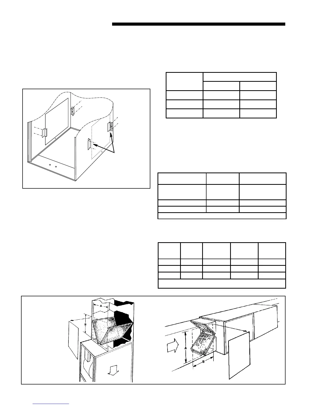
TYPICAL DOWNFLOW FURNACE
RETURN AIR FILTER INSTALLATIONS
Two filters are factory supplied for each downflow furnace.
These furnaces require high velocity type air filters. Down-
flow furnace filters must be located outside the furnace
cabinet. Typical installations are shown in Figure 25. Table
8 provides information for installation of the filter retaining
brackets shipped with downflow furnaces.
Table 6
MODELS
NUMBERS
CABINET
WIDTH
FILTER
QTY & SIZE
*DH2B060A9V3VA
*DH2B080A9V3VA
*DH2B080A9V4VA
17-1/2" 2 - 14" X 20" X 1"
*DH2C100A9V4VA 21" 2 - 16" X 20" X 1"
*DH2D120A9V5VA 24-1/2" 2 - 16" X 20 X 1"
* First letter may be "A" or "T"
Table 7
REAR
SIDE
CUT-OUT
ALTERNATE FILTE
CLIPS LOCATION
Figure 24
DOWNFLOW
Optional
BAYFLTR206
Door Kit
DOWNFLOW/
HORIZONTAL
Figure 25
ALTERNATE UPFLOW FILTER
CLIP / BRACKET INSTALLATION - KIT09224
1. Determine the location to be used. The furnace cabinet
has dimples for location of the alternate furnace clips
(Side return only). Pre-drill clearance holes with a
3/16" drill. Bottom return holes are pre-drilled.
2. Install the clips in front and rear of the desired location
using the screws provided. The filter clip with the leaf
spring mounts in the rear of the cabinet. See Figure 24.
Optional door
kit
BAYFLTR206
 Loading...