18-CD26D1-10 35
Installer’s Guide
HIGH ALTITUDE DERATE
Input ratings (BTUH) of these Furnaces are based on sea
level operation and should not be changed at elevations up to
2,000 ft.
If the installation is 2,000 ft. or above, the Furnace input rate
(BTUH) shall be reduced 4% for each 1,000 ft. above sea level.
The Furnace input rate shall be checked by clocking the gas
flow rate (CFH) and multiplying by the heating value ob-
tained from the local utility supplier for the gas being deliv-
ered at the installed altitude. Input rate changes can be
made by adjusting the Manifold Pressure (min 3.0 - max 3.7
in. W.C. - Natural Gas) or changing orifices (orifice change
may not always be required).
If the desired input rate can not be achieved with a change in
Manifold Pressure, then the orifices must be changed. LP
installations will require an orifice change.
IMPORTANT: Reinstall the replacement orifices to the same
depth as the orifices supplied with the equipment.
See Table 19 for help in selecting orifices if orifice change is
required. Furnace input rate and temperature rise should be
checked again after changing orifices to confirm the proper rate
for the altitude.
The vent length table on page 19 shows the required vent
lengths for installations at various altitudes. An optional
high altitude kit is available for installations above 5000
feet. Installations above 12,000 feet are not allowed.
Table 19
PART NUMBERS FOR REPLACEMENT ORIFICES
DRILL
SIZE
PART
NUMBER
DRILL
SIZE
PART
NUMBER
44
45
46
47
48
49
50
ORF00501
ORF00644
ORF00909
ORF00910
ORF01099
ORF00503
ORF00493
54
55
56
57
58
59
ORF00555
ORF00693
ORF00907
ORF00908
ORF01338
ORF01339
Turn the main Gas Valve toggle switch (See Figures 30 & 31)
within the unit to the “OFF” position. Turn the external gas
valve to “ON”. Purge the air from the gas lines. After purging,
check all gas connections for leaks with a soapy solution -- DO
NOT CHECK WITH AN OPEN FLAME. Allow 5 minutes
for any gas that might have escaped to dissipate.
LP Gas being heavier than air may require forced ventilation.
Turn the toggle switch on the Gas Valve in the unit to the “ON”
position.
If your application requires a high altitude pressure switch
use Table 20 to select the appropriate kit for your model
furnace.
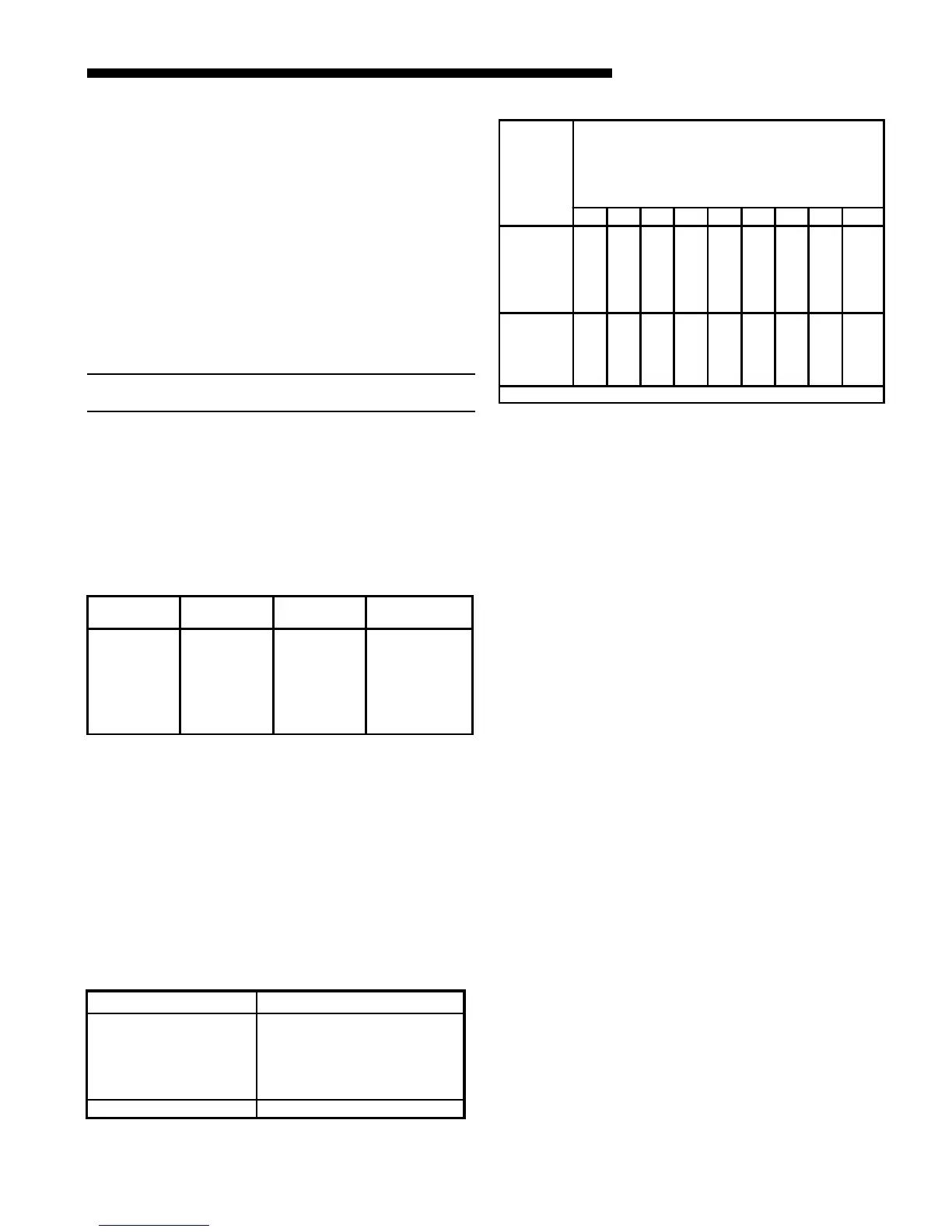
Orifice
Twist Drill
Size If
Installed
At Sea
Level
ALTITUDE ABOVE SEA LEVEL
and Orifice Required At Other Elevations
2000 3000 4000 5000 6000 7000 8000 9000 1000
42
43
44
45
46
47
42
44
45
46
47
48
43
44
45
47
47
48
43
44
45
47
47
49
43
45
46
47
48
49
44
45
47
48
48
49
44
46
47
48
49
50
45
47
48
49
49
50
46
47
48
49
50
51
47
48
50
50
51
52
54
55
56
57
58
54
55
56
58
59
55
55
56
59
60
55
55
57
59
60
55
56
57
60
61
55
56
57
60
62
55
56
58
61
62
56
56
59
62
63
56
56
59
63
63
56
57
60
63
64
From National Fuel Gas Code - Table F-4
Table 21
Table 20
High Altitude Kits Used With
BAYSWT08AHALTA
*UH2B/*DH2B080A9V3VA
*UH2B/*DH2B080A9V4VA
*UH2C/*DH2C100A9V4VA
*UH2C100A9V5VA
*UH2D/*DH2D120A9V5VA
BAYSWT10AHALTA *UH2B/*DH2B060A9V3VA
Installation of this furnace at altitudes above 2000 ft
(610m) shall be in accordance with local codes, or in the
absence of local codes, the National Fuel Gas Code, ANSI
Z223.1/NFPA 54 or National Standard of Canada, Natural
Gas and Propane Installation Code, CSA B149.1.
Installation of this furnace at altitudes above 2000 ft (610
m) shall be made in accordance with the listed high
Altitude Conversion Kit available with this furnace.
 Loading...