8 18-CD26D1-10
Installer’s Guide
The bottom panel of the upflow furnace must be removed for
bottom return air.
Remove the filter and lay the furnace on its back. Remove the
two 5/16" hex screws securing the bottom front channel to the
cabinet. Lower the front edge of the bottom front channel and
pull forward to remove the channel. The bottom return air
panel will now easily slide out of the cabinet. Reinstall the
bottom front channel and filter for upflow bottom return
installations.
UPFLOW INSTALLATION
Standoffs and screws (See Figure 4) are included with the
cased coils for attachment to the Furnace. There are clear-
ance alignment holes near the bottom of the coil wrapper.
Drill screws are used to engage the Furnace top flanges. The
standoff is inserted into the cabinet alignment hole. The drill
screws are inserted through the standoffs then screwed into
the Furnace flange. The coil is always placed downstream of
the Furnace airflow. The above instructions apply only if the
coil is on top of an upflow Furnace
DOWNFLOW INSTALLATION
HORIZONTAL INSTALLATION
The coil and Furnace must be fully supported when used in
the horizontal position. It is always recommended that an
auxiliary drain pan be installed under a horizontally in-
stalled evaporator coil or 90% Gas Furnace. Connect the
auxiliary drain line to a separate drain line (no trap is needed
in this line).
Three brackets (with screws) are included with downflow
furnaces for installtion to stabilize and secure the 2/4TXC
cased coil in the horizontal position. See Figure 8.
The cased coil is secured to the Furnace. The brackets mount
using the rear screws on the coil case. Use the screws provided
to secure the bracket to the Furnace. The remaining bracket
is placed as close to horizontal center as possible between the
coil and the Furnace, converted to horizontal, aligns and
attaches to the TXC coil.
The Furnace and the cased coil must be properly supported.
The Furnace may be installed in an attic or crawl space in the
horizontal position by placing the Furnace on the left side (as
viewed from the front in the vertical position). The horizontal
Furnace installation in an attic should be on a service
platform large enough to allow for proper clearances on all
sides and service access to the front of the Furnace (See
Figure 6 & Table 1). Line contact is only permissible between
lines formed by intersections of the top and two sides of the
furnace casing and building joists, studs, or framing.
The Furnace may be placed horizontally in a crawl space on a
pad or other noncombustible material which will raise the
unit for sufficient protection from moisture.
The Furnace must be supported at both ends and the
middle when installed horizontally. The Furnace must
also be elevated approximately 4-6 inches to allow
clearance for the condensate drain to exit the cabinet in
the horizontal position.
WARNING
!
FIRE HAZARD. DO NOT INSTALL THE FURNACE DIRECTLY
ON CARPETING, TILE OR OTHER COMBUSTIBLE MATE-
RIAL OTHER THAN WOOD FLOORING. FOR VERTICAL
DOWNFLOW APPLICATION, SUBBASE (BAYBASE205)
MUST BE USED BETWEEN THE FURNACE AND COMBUS-
TIBLE FLOORING. WHEN THE DOWNFLOW FURNACE IS
INSTALLED VERTICALLY WITH A CASED COIL, A SUB-
BASE IS NOT REQUIRED.
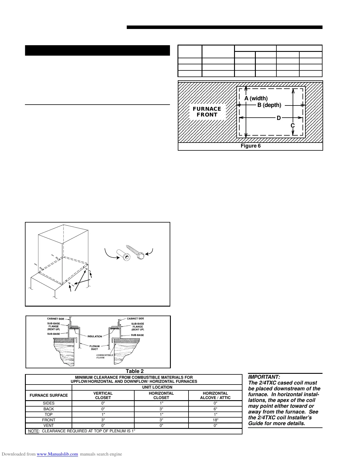
Table 1 Required floor opening: (DOWNFLOW)
CABINET
WIDTH
RETURN
DUCT WIDTH
FLOOR OPENING PLENUM OPENING
"A" "B" "C" "D"
17-1/2" 16-1/4" 16-5/8" 20-1/8" 15-5/8" 19-3/8"
21" 19-3/4" 20-1/8" 20-1/8" 19-1/8" 19-3/8"
24-1/2" 23-1/4" 23-5/8" 20-1/8" 22-5/8" 19-3/8"
INSTALLATION INSTRUCTIONS
Figure 5
UPFLOW
FURNACE
CASED
COIL
SCREW
(BOTH SIDES
STANDOFFS
(BOTH SIDES)
TANDOFFS (4)
DRILL SCREWS (
FOR VERTICAL
Figure 4
123456789012345678901234567890121234567890123456
1
2345678901234567890123456789012123456789012345
2345678901234567890123456789012123456789012345
2345678901234567890123456789012123456789012345
2345678901234567890123456789012123456789012345
2345678901234567890123456789012123456789012345
2345678901234567890123456789012123456789012345
2345678901234567890123456789012123456789012345
2345678901234567890123456789012123456789012345
2345678901234567890123456789012123456789012345
2345678901234567890123456789012123456789012345
2345678901234567890123456789012123456789012345
2345678901234567890123456789012123456789012345
2345678901234567890123456789012123456789012345
2345678901234567890123456789012123456789012345
2345678901234567890123456789012123456789012345
2345678901234567890123456789012123456789012345
2345678901234567890123456789012123456789012345
2345678901234567890123456789012123456789012345
2345678901234567890123456789012123456789012345
6
123456789012345678901234567890121234567890123456
FURNACE
FRONT
A (width)
B (depth)
C
D
Figure 6
MINIMUM CLEARANCE FROM COMBUSTIBLE MATERIALS FOR
UPFLOW/HORIZONTAL AND DOWNFLOW/ HORIZONTAL FURNACES
UNIT LOCATION
FURNACE SURFACE
VERTICAL
CLOSET
HORIZONTAL
CLOSET
HORIZONTAL
ALCOVE / ATTIC
SIDES 0" 1" 0"
BACK 0" 3" 6"
TOP 1" 1" 1"
FRONT 3" 3" 18"
VENT 0" 0" 0"
NOTE
: CLEARANCE REQUIRED AT TOP OF PLENUM IS 1"
Table 2
IMPORTANT:
The 2/4TXC cased coil must
be placed downstream of the
furnace. In horizontal instal-
lations, the apex of the coil
may point either toward or
away from the furnace. See
the 2/4TXC coil Installer's
Guide for more details.
 Loading...