18-CD26D1-10 11
Installer’s Guide
Carbon monoxide, fire or smoke can cause serious bodily
injury, death, and/or property damage.
A variety of potential sources of carbon monoxide can be found
in a building or dwelling such as gas-fired clothes dryers, gas
cooking stoves, water heaters, furnaces and fireplaces. The
U.S. Consumer Product Safety Commission recommends
that users of gas-burning appliances install carbon monoxide
detectors as well as fire and smoke detectors per the manu-
factures installation instructions to help alert dwelling
occupants of the presence of fire, smoke or unsafe levels of
carbon monoxide. These devices should be listed by Under-
writers Laboratories, Inc. Standards for Single and Multiple
Station Carbon Monoxide Alarms, UL 2034 or CSA Interna-
tional Standard, Residential Carbon Monoxide Alarming
Devices, CSA 6.19.
NOTE: The manufacturer of your Furnace DOES NOT test
any detectors and makes no representations regarding any
brand or type of detector.
All return air duct systems should provide for installation of
return air filters.
PREPARATION FOR UPFLOW BOTTOM AND SIDE RETURN
AIR FILTER INSTALLATION
All return air duct systems should provide for installation of
return air filters.
1. Determine the appropriate position to set the furnace in
order to existing supply and return ductwork.
2. The return air filter and rack are shipped in either the
bottom or side location. Remove the filter and filter rack
by first turning the two latches on the blower door and
tilting the door forward to remove. Remove the filter by
sliding it out of the rack. Compress the spring loaded
filter rack to disengage the retaining pins/screws from
the furnace sides and slide the filter rack out.
The filter rails are spring loaded for automatic adjust-
ment to allow standard size, locally obtainable replace-
ment filters. The filter rack itself slides to adjust to the
required width needed for bottom or side return (See
Figure 15).
3. For upflow side return installations, remove the insulation
around the opening in the blower compartment.
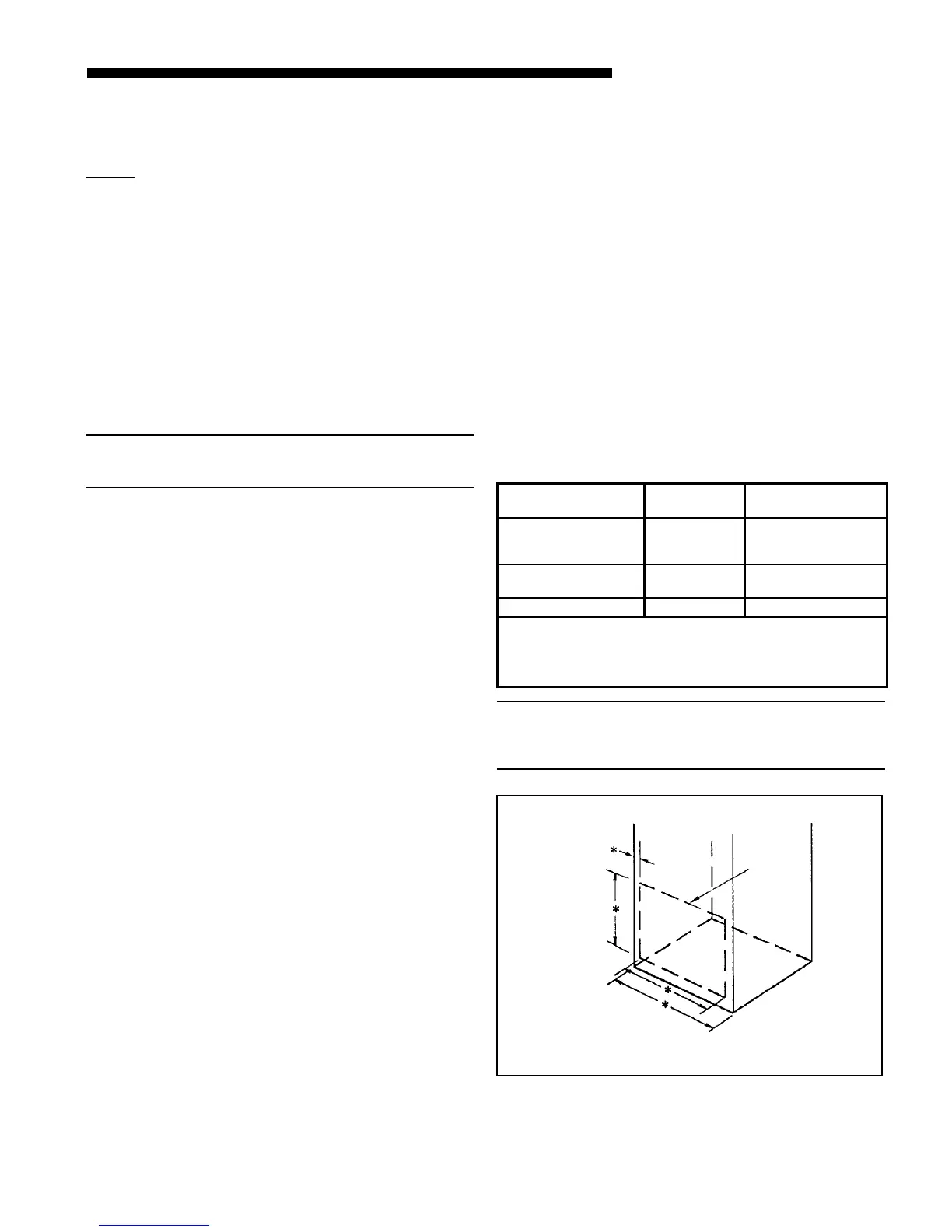
4. The side panels of the upflow furnace include locating
notches that are used as guides for cutting an opening for
return air, refer to Figure 13 and the outline drawing on
page 6 for duct connection dimensions for various
furnaces.
5. If a 3/4" flange is to be used for attaching the air inlet
duct, add to cut where indicated by dotted lines in
Figure 13. Cut corners diagonally and bend outward to
form flange.
6. If flanges are not required, and a filter frame is installed,
cut between locating notches (See Figure 13).
7. The bottom panel of the upflow furnace must be removed
for bottom return air. After removing the filter and filter
rack, lay the furnace on its back. Remove the two 5/16"
hex screws securing the front of the bottom channel to the
cabinet. Rotate the channel downward (or remove by
lowering the front edge of the channel and pulling
forward).
Return Air Filters
TYPICAL UPFLOW RETURN AIR FILTER INSTALLATIONS
Filters are factory supplied for these furnaces. These fur-
naces require high velocity type air filters. The filters may be
installed within the furnace blower compartment for UP-
FLOW furnaces in either a BOTTOM or SIDE (left side or
right side) return air inlet. Some filters may need to be
trimmed for side or bottom filter use.
Table 5
MODELS
NUMBERS
CABINET
WIDTH
FILTER
QTY & SIZE
*UH2B060A9V3VA
*UH2B080A9V3VA
*UH2B080A9V4VA
17-1/2" 1 - 17" X 25" X 1"
*UH2C100A9V4VA
*UH2C100A9V5VA
21" 1 - 20" X 25" X 1"
*UH2D120A9V5VA 24-1/2" 1 - 24" X 25 X 1"
*First letter may be "A" or "T"
**NOTE: For upflow 5 ton airflow models where the airflow
requirement exceeds 1800 CFM - Modles will require return air
openings and filters on: (1) both sides, or (2) one side and the
bottom, or (3) just on the bottom
NOTE: For upflow 5 ton airflow models where the airflow
requirement exceeds 1800 CFM - Models will require return
air openings and filters on: (1) both sides, or (2) one side and
the bottom, or (3) just the bottom.
UPFLOW FURNACE ONLY
*
SEE OUTLINE DRAWING
FRONT
of Furnace
LOCATING
NOTCHES
PROVIDED FOR
SIDE RETURN
CUTOUT
Figure 13
Where there is no complete return duct system, the
return connection must be run full size from the Fur-
nace to a location outside the utility room, basement,
attic, or crawl space.
Do Not install return air through the back of the Furnace
cabinet.
Slide the bottom return air panel out of the cabinet.
Rotate the front channel to its original position and
reinstall the two 5/16” screws.
8. The horizontal installation of the upflow furnace
requires an external filter section. Do NOT use the
bottom return filter within the furnace. Filter kits
are available for horizontal applications.
9. Connect duct work to furnace. See Outline Drawing for
supply and return duct size and location. Flexible duct
connectors are recommended to connect both supply and
return air ducts to the furnace. If only the front of the
furnace is accessible, it is recommended that both supply
and return air plenums are removable.
 Loading...