32 18-CD26D1-10
Installer’s Guide
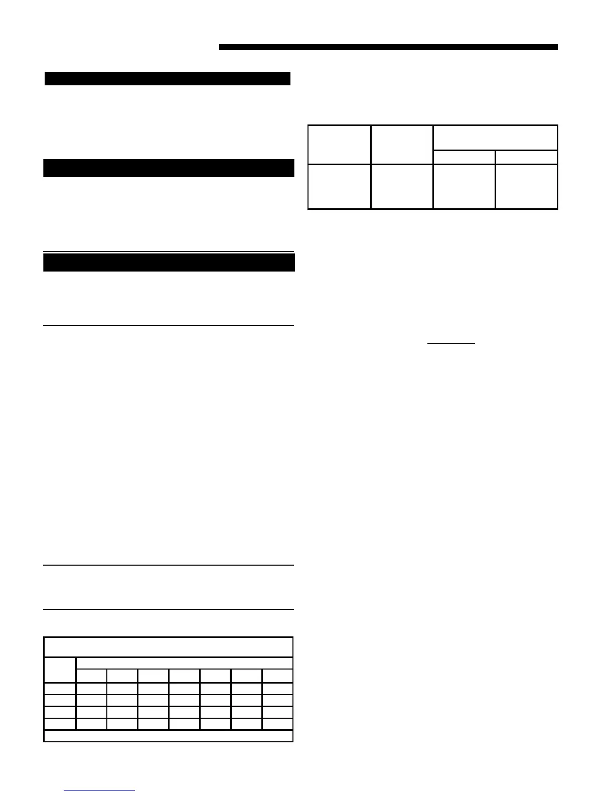
Table 16
ORIFICE SIZES
INPUT
RATING
BTUH
NUMBER
OF
BURNERS
MAIN BURNER ORIFICE
DRILL SIZE
NAT. GAS LP GAS
60,000
80,000
100,000
120,000
3
4
5
6
45
45
45
45
56
56
56
56
Combustion and Input Check
(See also High Altitude Derate, page 34)
1. Make sure all gas appliances are off except the furnace.
2. Clock the gas meter with the furnace operating (deter-
mine the dial rating of the meter) for one revolution.
3. Match the “Sec” column in the gas flow (in cfh) Table 13
with the time clocked.
4. Read the “Flow” column opposite the number of seconds
clocked.
5. Use the following factors
if necessary:
For 1 Cu. Ft. Dial Gas Flow CFH =
Chart Flow Reading ÷ 2
For 1/2 Cu Ft. Dial Gas Flow CFH =
Chart Flow Reading ÷ 4
For 5 Cu. Ft. Dial Gas Flow CFH =
10X Chart Flow Reading ÷ 4
6. Multiply the final figure by the heating value of the gas
obtained from the utility company and compare to the
nameplate rating. This must not exceed the nameplate
rating.
Gas Valve Adjustment
Changes can be made by adjusting the manifold pressure
(See Table 17), or changing orifices (orifice change may
not always be required). To adjust the manifold pres-
sure:
1. Turn off all electrical power to the system.
2. Attach a manifold pressure gauge with flexible tubing to
the outlet pressure boss marked “OUT P” on White-
Rodgers gas valve model 36G or 36J. See Figure 57A for
White-Rodgers gas valve model 36J. See Figure 57B for
White-Rodgers gas valve model 36G.
3. Loosen (Do Not remove) the pressure tap test set screw
one turn with 3/32" hex wrench.
a. The pressure tap adjustment kit (KIT07611)
contains a 3/32" hex wrence, a 5/16" hose and a
connector and can be ordered through Global Parts.
4. Turn on system power and energize valve.
The upflow/horizontal furnace is shipped standard for left
side installation of gas piping. A knockout is provided on the
right side for an alternate gas piping arrangement. See Figure
54.
The installation of piping shall be in accordance with piping
codes and the regulations of the local gas company. Pipe joint
compound must be resistant to the chemical reaction with
liquefied petroleum gases.
Refer to piping Table 15, for delivery sizes. Connect gas
supply to the unit, using a ground joint union and a manual
shut-off valve as shown in Figures 43 & 44. National codes
require a condensation drip leg to be installed ahead of the
controls as shown in Figures 55 & 56.
The furnace and its individual shut-off valve must be discon-
nected from the gas supply piping system during any pressure
testing of that system at test pressures in excess of 1/2 psig
(3.5 kPa).
The furnace must be isolated from the gas supply piping by
closing its individual manual shut-off valve during any
pressure testing of the gas supply piping system at test
pressures equal to or less than 1/2 psig (3.5 kPa).
NOTE: Maximum pressure to the gas valve for natural gas
is 13.8" W.C. Minimum pressure is 5.0" W.C. Maximum
pressure to the gas valve for propane is 13.8" W.C. Mini-
mum pressure is 11.0" W.C.
Table 15
NATURAL GAS ONLY
TABLE OF CUBIC FEET PER HOUR OF GAS
FOR VARIOUS PIPE SIZES AND LENGTHS
PIPE
SIZE
LENGTH OF PIPE
10 20 30 40 50 60 70
1/2 132 92 73 63 56 50 46
3/4 278 190 152 130 115 105 96
1 520 350 285 245 215 195 180
1-1/4 1050 730 590 520 440 400 370
This table is based on Pressure Drop of 0.3 inch W.C. and 0.6 SP.GR. Gas
▲
WARNING
!
AZARD OF EXPLOSION!
EVER USE AN OPEN FLAME TO DETECT GAS LEAKS.
XPLOSIVE CONDITIONS MAY OCCUR. USE A LEAK TEST
OLUTION OR OTHER APPROVED METHODS FOR LEAK
ESTING. FAILURE TO FOLLOW RECOMMENDED SAFE LEA
EST PROCEDURES COULD RESULT IN DEATH OR SERIOU
NJURY OR EQUIPMENT OR PROPERTY-ONLY-DAMAGE.
Gas Piping
WARNING
!
HAZARD OF EXPLOSION
DO NOT USE SEMI-RIGID METALLIC GAS CONNECTORS
(FLEXIBLE GAS LINES) WITHIN THE FURNACE CABINET.
FAILURE TO FOLLOW THIS WARNING COULD RESULT IN
PROPERTY DAMAGE, PERSONAL INJURY OR DEATH.
WARNING
!
HAZARD OF EXPLOSION
REPLACE AND/ OR TIGHTEN ALL PLUGS REMOVED OR
LOOSENED WHEN ADJUSTING GAS PRESSURE. LEAK
CHECK THE FITTINGS BEFORE PLACING THE FURNACE
INTO REGULAR SERVICE.
FAILURE TO FOLLOW THIS WARNING COULD RESULT IN
FIRE, EXPLOSION, PROPERTY DAMAGE, OR DEATH.
All gas fittings must be checked for leaks using a soapy solution
before lighting the furnace. DO NOT CHECK WITH AN
OPEN FLAME!
 Loading...