24
VAV-SVX08R-EN
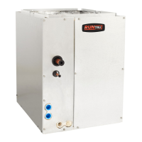
Bracket Locations
Chilled Water Sensible Cooling Terminal
Units
Figure 16. Bracket locations — cooling only unit, and
unit with hot water coil
41,2 [1045]
27,0 [685]
Primary Airflow
Airflow
Plenum Inlet
Airflow
Discharge
Outlet
Hot Water Coil
(not present on cooling-only units)
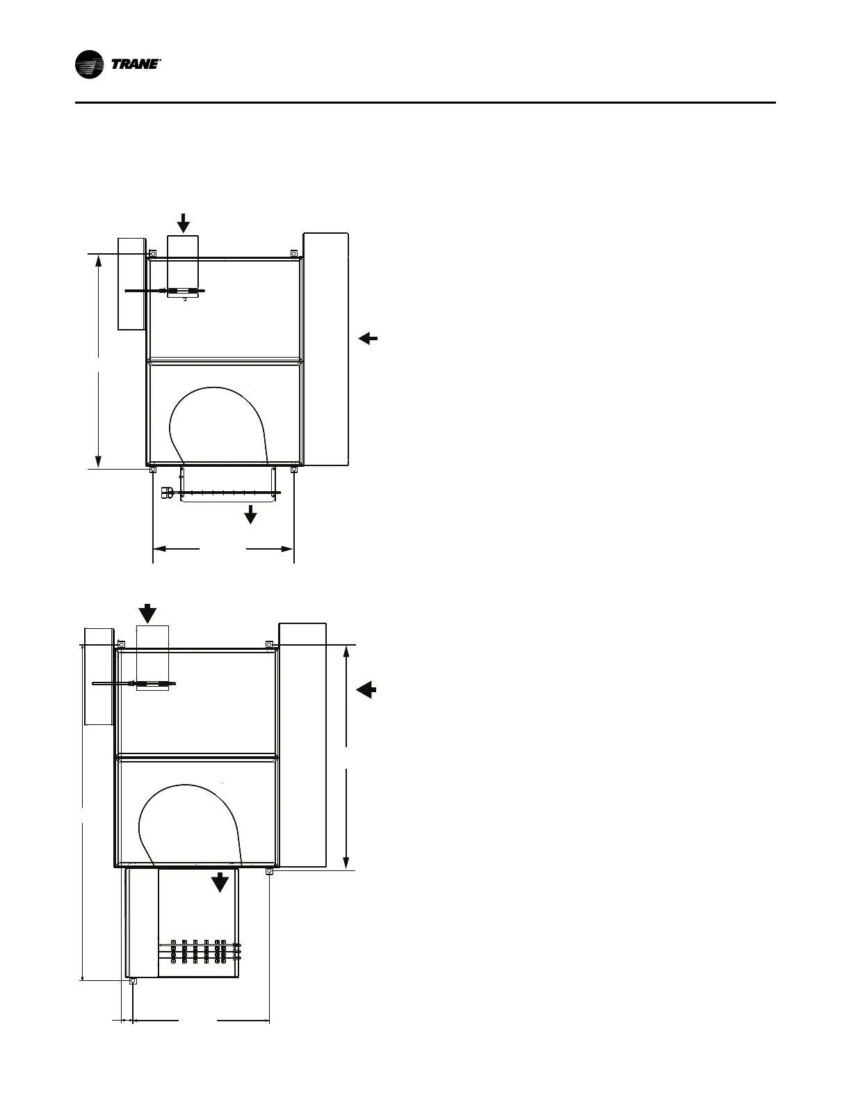
Figure 17. Bracket locations — electric heat unit
24,9 [631]
61,2 [1553]
2,1 [53]
Primary Airflow
Airflow
Plenum Inlet
Airflow
Discharge
Outlet
41,2
[1045]
Duct Connections
All VariTrane™ units should be provided with a
minimum of 1.5-duct diameters of straight duct prior to
the inlet of the unit. It is recommended that at least 48
inches of straight duct be provided from the discharge
of the units prior to any take-offs or transitions.
IImmppoorrttaanntt:: This is a requirement for electric heat fan-
powered units used in applications with
100% downward discharge.
In order to maintain good air distribution
over the elements and not create
turbulence which could cause a limit cutout
there should be four feet of ductwork,
consistent of the discharge dimensions of
the heater. downstream of the reheat coil
prior to any diffuser takeoffs for
VariTrane
™
electric coils.
1. After all connections are made, check that the entire
ductwork system is airtight. In some high-pressure
systems, duct sealer may be necessary.
NNoottee:: All inlet duct on the VAV boxes are sized
approximately 0.125 inches smaller in
diameter than the nominal size in order to
allow the incoming duct to slide over the inlet
of the VAV box.
2. Provide insulation around the entire inlet collar (all
the way to the unit casing).
NNoottee:: Use caution not to damage the flow tubes
when making ductwork connections or
insulating.
3. Cut slits in the insulation for the flow tubes and
secure with duct tape.
4. If the unit is to be installed in a location with high
humidity, external insulation around the heating
coil should be installed as required.
Water Coil Connections
NNootteess:: The following coils have 0.375 inches OD water
coil piping connections.
• Single Duct 1-row coils (inlet sizes 05, 05, 06,
08 or 10 only)
• Low Height Parallel Inlet 1-row
• Low Height Parallel Discharge 1-row
All others require a 0.875 inches OD water coil
piping connections.
1. If necessary, you can change the coil connection
from left-handed to right-handed (and vice-versa)
by disconnecting the coil from the unit and rotating
the coil like a steering wheel 180°.
NNoottee:: The exception is that the coil connection
cannot be changed on parallel fan powered
unit with hot water coil on plenum inlet.
2. Use port at the bottom for inlet and top for outlet on
UUnniitt IInnssttaallllaattiioonn
 Loading...