26
VAV-SVX08R-EN
Chilled Water Sensible Cooling
Terminal Units Moisture Sensor
Installation
In most applications, the water supplied to this local
cooling coil is controlled to a temperature above the
dew point in the zone. This avoids moisture in the air
from condensing on the coil, so it operates dry and
provides only sensible cooling. All dehumidification
must then be provided by the dedicated outdoor-air
unit. Trane chilled water sensible cooling terminal units
are built with a drip pan located beneath and above the
cooling coil, with a moisture sensor installed, to detect
and prevent any moisture from getting on the ceiling
beneath the units or into the occupied space below.
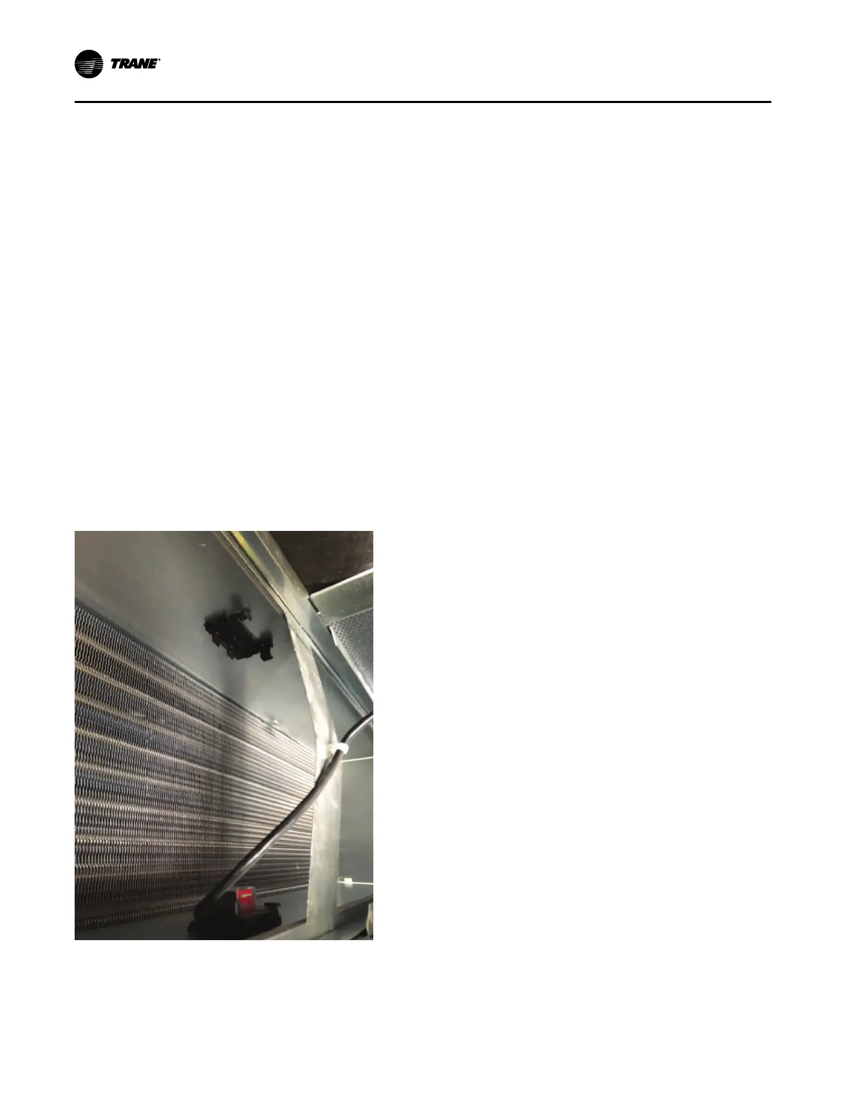
Sensible cooling units are designed so that the unit can
be flipped 180 degrees for right and left hand
orientation. They are configured as left hand from the
factory with a moisture sensor installed to a bracket on
the bottom of the drip pan. If installed as a right hand
unit the moisture sensor will need to be moved to the
bracket provided (shown in the following figure) so that
the moisture sensor is on the bottom of the unit for
proper moisture detection.
Figure 19. Moisture sensor installation and additional
bracket shown in cooling coil drip pan
Unit Accessibility
• Single-duct and dual-duct units provided with hot
water reheat have an access panel located on the
side of the water coil. All other single-duct and dual-
duct units are provided without access, as all
functioning components are external to the unit.
• Fan-powered terminals are provided with a sliding
side access.
• Low-height terminal units have a removable
bottom panel.
Clearances
For proper service, it is recommended that at least 3
inches” of side clearance be provided to service and
access single-duct and dual-duct terminals units.
• Fan-powered VAV units have a plenum inlet that
must be clear of obstructions. Allow at least 36
inches of clearance in front of the side access and
plenum opening.
• Low-height fan-powered terminals require the
same plenum clearance requirement that applies to
the standard fan-powered units. However the
access to the internal components is located on the
bottom of the unit.
• Fan-powered VAV units with Suppressor attenuator
requires at least 4.5 inches (6 inches preferred)
clearance above the plenum opening.
• Fan-powered VAV units with Thinline Suppressor
attenuator requires at least 4.5 inches (6 inches
preferred) clearance at plenum openings.
It is also recommended that 6 inches of clearance be
provided to the top and bottom of all the units.
NNoottee:: The minimum clearance for controls and heater
controls should be 36 inches for all models
except units with 575-volt electric heaters, which
require 48 inches of clearance. NEC
™
and/or
local codes override all clearance requirements.
Mounting Actuator
IImmppoorrttaanntt:: When installing or replacing the actuator
tighten the actuator set screw per the
manufacturer’s instructions. Failure to
follow the manufacturer’s specifications
may result in unit malfunction.
Trane offers a factory-mounted actuator with a 90-
second drive time. The actuator drives 1° per second. A
field-installed actuator may be used if desired. The
actuator shaft has a 0.5 inch diameter and is designed
to travel clockwise to close the damper and counter-
clockwise to open the damper. There is an indicator on
the end of the actuator shaft that can be used to
determine the position of the damper.
Stand-alone Units
Stand-alone UCM 4.2
When there is no communication to the UCM control
and the unit is in the stand-alone mode the control
UUnniitt IInnssttaallllaattiioonn
 Loading...