VAV-SVX08R-EN
27
action is determined by the auxiliary temperature
sensor located on TB3-5 and TB3-6 terminals on the
UCM board. In order for the auxiliary sensor to
determine the control action (heat, cool) it must be
located in the supply duct, upstream of the VAV unit.
The auxiliary temperature is then compared to the zone
temperature. If the supply air temperature is 10
degrees above the zone temperature, then the control
action will be heat. If the supply air temperature is less
than or equal to the zone temperature, then the control
action will be cool. If the supply air temperature is
between the zone temperature and the zone
temperature + 10ºF (5.5°C) [zone temperature < supply
air temperature < zone temperature + 10ºF] (5.5°C), the
control action remains the same and the UCM controls
to the minimum flow set point. If an auxiliary sensor is
not installed the UCM will retain the last control action
in effect.
Stand-alone VV550 LonTalk Control
When there is no communication to the VV550 control
and the unit is in the stand-alone mode the control
action is determined by the auxiliary temperature
sensor located on TB3-5 and TB3-6 terminals on the
VV550 board. The control must also be configured
through the Inputs Tab of Analog Input 4 as Primary
Supply Air Sensor. In order for the auxiliary sensor to
determine the control action (heat, cool) it must be
located in the supply duct, upstream of the VAV unit.
The auxiliary temperature is then compared to the zone
temperature. If the supply air temperature is 10
degrees above the zone temperature, then the control
action will be heat. If the supply air temperature is less
than or equal to the zone temperature, then the control
action will be cool. If the supply air temperature is
between the zone temperature and the zone
temperature + 10ºF (5.5°C) [zone temperature < supply
air temperature < zone temperature + 10ºF] (5.5°C), the
control action remains the same and the UCM controls
to the minimum flow set point. If an auxiliary sensor is
not installed the UCM will retain the last control action
in effect.
Stand-alone UC400
When there is no communication to the UC400 control
and the unit is in the stand-alone mode the control
action is determined by the auxiliary temperature
sensor located on AI5 terminals on the UC400 control.
This input may have to be changed from AI4 (Discharge
Air Input) as wired from the factory. In order for the
auxiliary temperature sensor to determine the control
action (heat, cool) it must be located in the supply duct,
upstream of the VAV unit. The auxiliary temperature is
then compared to the zone temperature. If the supply
air temperature is 10°F above the zone temperature,
then the control action will be heat. If the supply air
temperature is less than or equal to the zone
temperature, then the control action will be cool. If the
supply air temperature is between the zone
temperature and the zone temperature +10°F (5.5°C)
[zone temperature < supply air temperature < zone
temperature +10°F] (5.5°C), the control action remains
the same and the UC400 controls to the minimum flow
set point. If an auxiliary sensor is not installed the
UC400 will retain the last control action in effect.
Stand-alone UC210
When there is no communication to the UC210 control
and the unit is in the stand-alone mode the control
action is determined by the auxiliary temperature
sensor located on AI3 terminals on the UC210 control.
From the factory, this input is configured for discharge
air temperature and needs to be field reconfigured as
supply air temperature using Tracer® TU. In order for
the auxiliary temperature sensor that is configured for
supply air temperature to determine the control action
(heat, cool) it must be located in the supply duct,
upstream of the VAV unit. The supply air temperature
is then compared to the zone temperature. If the supply
air temperature is 10°F above the zone temperature,
then the control action will be heat. If the supply air
temperature is less than or equal to the zone
temperature, then the control action will be cool. If the
supply air temperature is between the zone
temperature and the zone temperature +10°F (5.5°C)
[zone temperature < supply air temperature < zone
temperature +10°F] (5.5°C), the control action remains
the same and the UC210 controls to the minimum flow
set point. If an auxiliary temperature sensor is not
installed and configured for supply air temperature, the
UC210 will retain the last control action in effect.
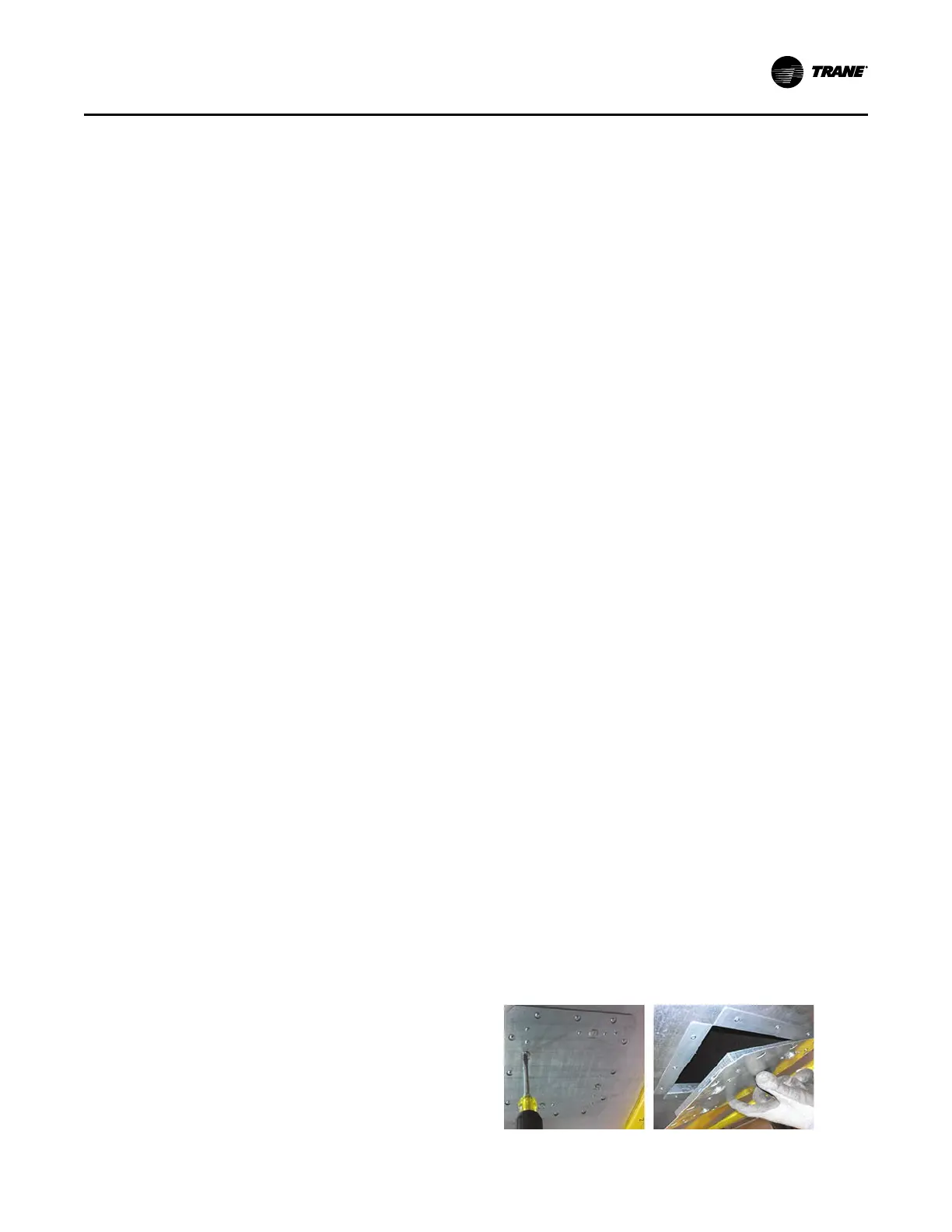
Bottom Access
An optional bottom access can be provided in the
casing of fan powered series or parallel terminal unit.
The 22-gauge door is lined with 1 inch, 26-gauge, dual
wall insulation and thermal lined with 1 inch – 1 lb.
density fiberglass insulation with a 3.85 R-value.
Each door includes 1 to 6 cam locks that are used to
secure the door to the casing.
The cam lock engages a metal encapsulated frame on
the unit that encloses the unit insulation to prevent air
erosion.
The cam lock engagements are interlocked using a flat
head screwdriver. Once unlocked, the entire door
assembly can be removed for access.
Figure 20. Bottom access
UUnniitt IInnssttaallllaattiioonn
 Loading...