WC-IOM-7 • Packaged Heat Pump 27
Installation
Note: Resistance in excess of 2.5 ohms per conductor can cause deviations in
the accuracy of the controls.
2. Ensure that the wiring between controls and the unit’s termination point does
not exceed two and a half (2.5) ohms/conductor for the length of the run.
3. Do not run the electrical wires transporting DC signals in or around conduit
housing high voltage wires.
Table 3. DC Conductors Zone Sensor Module wiring
Distance from Unit to Control Recommended Wire Size
0 - 150 feet 22 gauge
0 - 45.7 m .33 mm2
151 - 240 feet 20 gauge
46 - 73.1 m .50 mm2
241 -385 feet 18 gauge
73.5 - 117.3 m .75 mm2
386 - 610 feet 16 gauge
117.7 - 185.9 m 1.3 mm2
611 - 970 feet 14 gauge
186.2 - 295.7 m 2.0 mm2
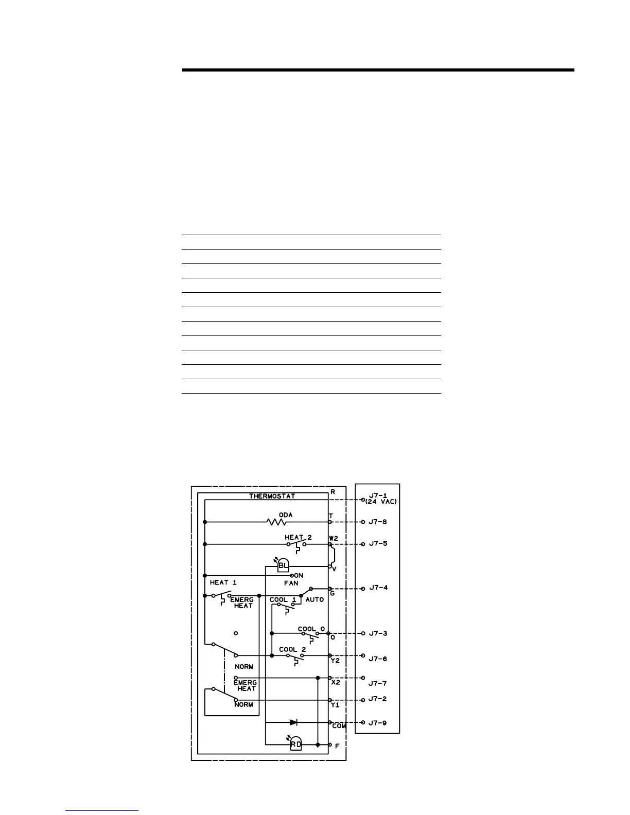
Figure 11. Reliatel conventional thermostat field wiring diagram
RTRM
 Loading...


