13
Mounting
3
Using the center-to-center spacing of the mounting holes, mark
the locations for installation.
4
Secure the remote to its permanent location with user-supplied
hardware. Tighten by hand to reduce the possibility of cracking
the remote module at its mounting points.
5
Connect the remote’s wired connector to the inverter’s RJ11 port
labeled “REMOTE”.
6
Set the inverter’s main power switch to the REMOTE (||) position.
7
Test the connection and operation by pressing ON/OFF until the
green status LED shows on the remote module.
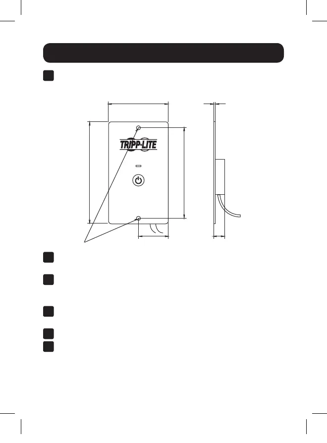
STATUS
ON/OFF
PINVRM
2.539 in. (65 mm)
Ø0.157 in. (4 mm)
3.818 in. (97 mm)
4.284 in. (109 mm)
0.104 in. (3 mm)
Ø1.269 in. (32 mm) 0.492 in. (13 mm)
*All mounting dimensions are accurate to +/- 0.1 inch (2.5 mm).
2
The following mounting dimensions* should be used when
installing the remote to a permanent mounting location:
19-04-283-9338A1.indb 13 5/2/2019 3:49:32 PM

 Loading...