5. aSSeMBlY STePS
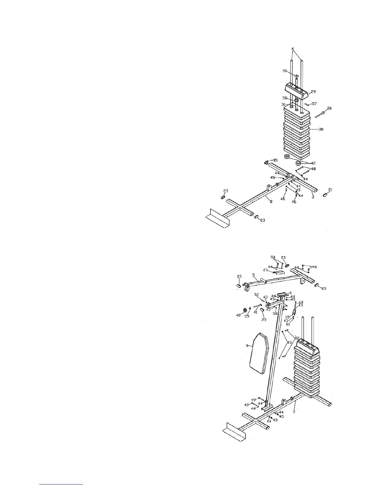
STeP 1
Note: Four3/8”x19mmWashers(44)andfour3/8”x1”Bolts(46)
have been attached to the Guide Tubes (4). Please remove these first,
then follow the assembly steps.
• SlideoneRubberRing(42)ontoeachoftheGuideTubes(4).
Placethe40x80mmEndCap(21)intotheHorizontalBeam
(3)andtheninserttheGuideTubes(4)intotheHorizontalBeam
(3).Securethisassemblywithtwo3/8”x19mmWashers(44)
andtwo3/8”x1”Bolts(46).
• ConnecttheT-Tube(2)andtheHorizontalBeam(3)withtwo
3/8”x4”Bolts(48),four3/8”x19mmWashers(44)andtwo
3/8”Nuts(45).Tightentheassembly.
• SlidethenineWeightStacks(30)andTopPlate(29)ontothe
two Guide Tubes (4).
• AttachtheFixingBushing(58)ontotheSelectorBar(31).Push
theFixingPin(57)throughtheholeintheFixingBushing(58)
and the first hole of the Selector Bar (31). Now slide the Top
Plate(29)ontotheFixingBushing(58).
• PlacetheSelectorBar(31)intotheWeightStack(30)andplace
theWasher(56)ontotheTopPlate(29).InserttheWeightStack
Pin(26)intotheWeightStack(30).
STeP 2
• AttachtheSupportTube(1)totheT-Tube(2)usingtwo
3/8”x82mmBolts(49),two3/8”Nuts(45)andfour3/8”x
19mm Washers (44).
• SecuretheBackCushion(9)totheSupportTube(1)usingtwo
5/16”x1-3/4”Bolts(52)andtwo5/16”x16mmWashers(43).
• AttachtheRidgeTube(5)ontothetopofSupportTube(1),
securingthemtogetherwiththeFittingPlate(27),two3/8’x2”
Bolts(54),four3/8”x19mmWashers(44)andtwo3/8”Nuts
(45).
• ConnecttheRidgeTube(5)andthetwoGuideTubes(4);
securingthemwithtwo3/8”x1”Bolts(46)andtwo3/8”x
19mm Washers (44).
• AttachthetwoPulleyBrackets(15)totheSupportTube(1),
securingthemwithtwo5/16”x2-3/4”bolts(69),four
5/16”x16mmWashers(43)andtwo5/16”Nuts(61).
• AttachthePressPin(41)totheSupportTube(1)withone
5/16”x1-3/4”Bolt(52),two5/16”x16mmWashers(43)and
one Nut (61).
• AttachKnob(40)and3/8”x1”Washer(59)tothePressPin
(41).
 Loading...