Adjustments
Skid Shoes
The snow thrower skid shoes are adjusted upward at the factory
for shipping purposes. Adjust them downward, if desired, prior
to operating the snow thrower.
CAUTION: It is not recommended that you operate
this snow thrower on gravel as it can easily pick up and
throw loose gravel, causing personal injury or damage
to the snow thrower and surrounding property.
For close snow removal on a smooth surface, raise skid
shoes higher on the auger housing.
Use a middle or lower position when the area to be cleared
is uneven, such as a gravel driveway
NOTE: If you choose to operate the snow thrower on a gravel
surface, keep the skid shoes in position for maximum clearance
between the ground and the shave plate.
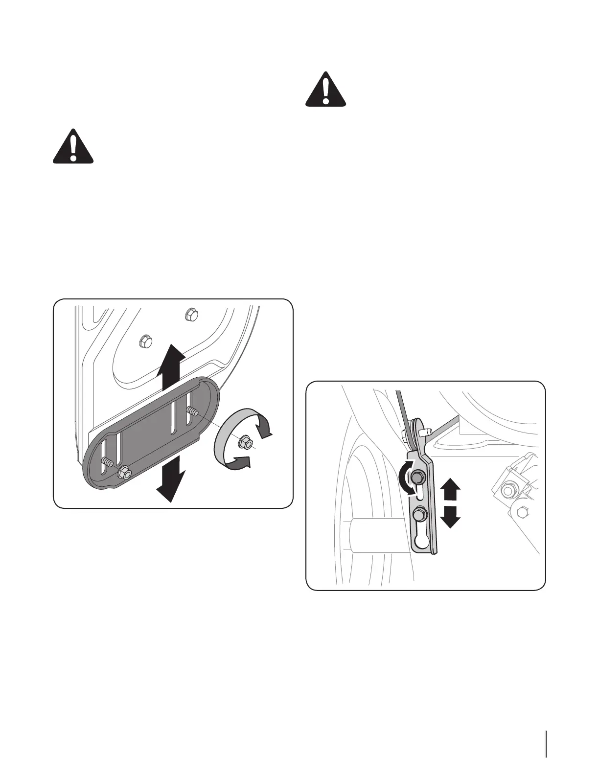
To adjust the skid shoes:
Loosen the four hex nuts (two on each side) and carriage
Make certain the entire bottom surface of skid shoe is 2.
against the ground to avoid uneven wear on the skid shoes.
Retighten nuts and bolts securely.3.
Auger Control
WARNING! Prior to operating your snow thrower,
carefully read and follow all instructions below.
Perform all adjustments to verify your snow thrower
is operating safely and properly.
Check the adjustment of the auger control as follows:
When the auger control is released and in the disengaged
should NOT be tight.
In a well-ventilated area, start the snow thrower engine. 2.
While standing in the operator’s position (behind the snow 3.
thrower), engage the auger.
Allow the auger to remain engaged for approximately ten
several times.
5.
walk to the front of the machine.
Confirm that the auger has completely stopped rotating
and shows NO signs of motion. If the auger shows ANY
signs of rotating, immediately return to the operator’s
position and shut off the engine. Wait for ALL moving parts
to stop before re-adjusting the auger control.
To readjust the control cable, loosen the upper hex nut 7.
on the auger cable bracket. Position the bracket upward
to provide more slack (or downward to increase cable
Retighten the upper hex nut.8.
been achieved.
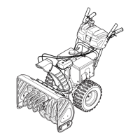
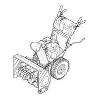
Figure 3-15
Figure 3-14
11se c t i O n 3 — as s e M b l y & se t -up

 Loading...