11
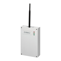
progress. The LEDs cycle from top to bottom and then bottom to top until the 3G4010/LE4010 connects to a
carrier with a signal strength above 7 CSQ (minimum of bottom signal strength LED on solid).
Red Blue
Yellow/Green
(Top)
Yellow/Green
(Bottom)
FLASH ON OFF OFF OFF
OFF FLASH ON OFF OFF
OFF OFF FLASH ON OFF
OFF OFF OFF FLASH ON
OFF OFF FLASH ON OFF
OFF FLASH ON OFF OFF
FLASH ON OFF OFF OFF
Once this is completed, the 3G4010/LE4010 proceeds to Step 4.
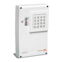
Step 4 - Acquire C24 Communications Programming
The red LED is on solid and the blue LED flashes. The flashing blue LED indicates that the 3G4010/LE4010
has requested programming from C24 Communications and is waiting for a response.
Red Blue
Yellow/Green
(Top)
Yellow/Green
(Bottom)
ON FLASHING - -
Once remote programming is completed, the blue LED switches to solid and the 3G4010/LE4010 proceeds to
Step 5.
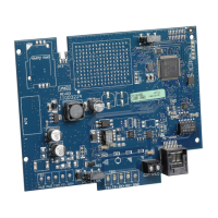
Step 5 – Receiver Initialization
The red and blue LED’s are both on solid and the signal strength LEDs are off.
Red Blue
Yellow/Green
(Top)
Yellow/Green
(Bottom)
ON ON OFF OFF
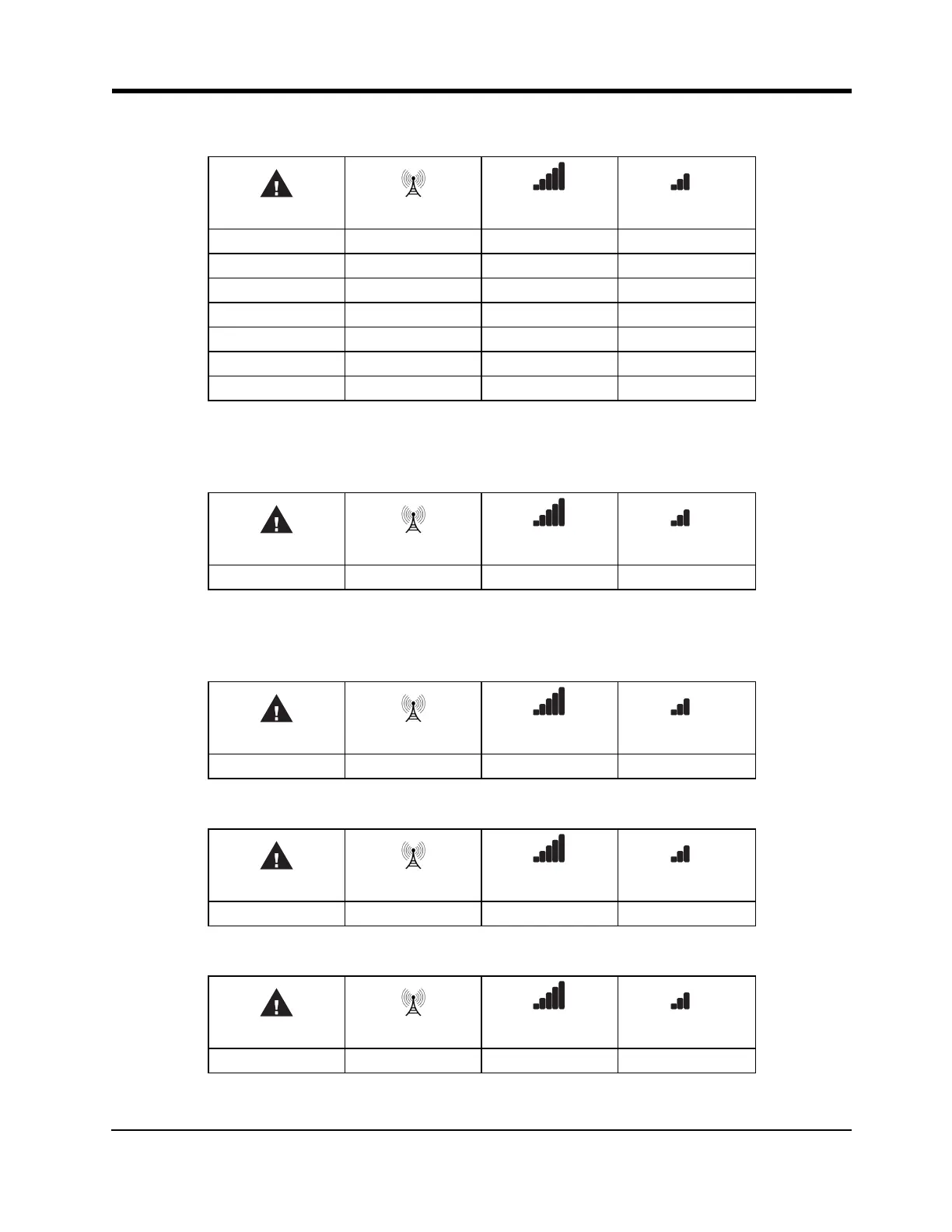
When the 3G4010/LE4010 sends a request to communicate with the central station, the top signal strength
LED begins flashing.
Red Blue
Yellow/Green
(Top)
Yellow/Green
(Bottom)
ON ON FLASHING OFF
When the central station communicates back to the 3G4010/LE4010, the top signal strength LED turns on
solid.
Red Blue
Yellow/Green
(Top)
Yellow/Green
(Bottom)
ON ON ON OFF
3G4010/LE4010 Installation Manual
 Loading...