MAX-M10S-Integration manual
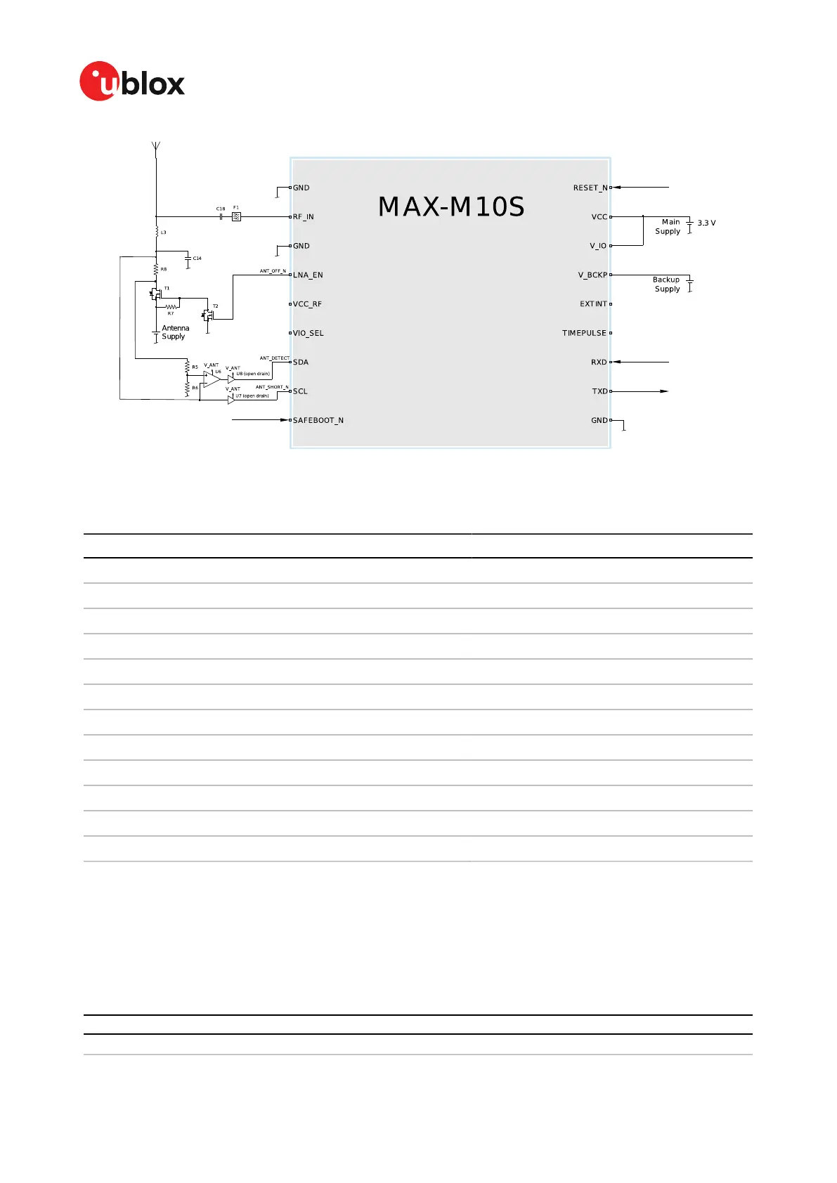
Figure 39: 3-pin antenna supervisor design
The 3-pin antenna supervisor configuration required for the Figure 39 reference design is listed in
Table 35.
Configuration key Value
CFG-I2C-ENABLED 0 (false)
CFG-HW-ANT_CFG_VOLTCTRL 1 (true), default (no configuration required)
CFG-HW-ANT_SUP_SWITCH_PIN 7, default (no configuration required)
CFG-HW-ANT_CFG_SHORTDET 1 (true)
CFG-HW-ANT_CFG_SHORTDET_POL 0 (false)
CFG-HW-ANT_SUP_SHORT_PIN 3
CFG-HW-ANT_CFG_OPENDET 1 (true)
CFG-HW-ANT_CFG_OPENDET_POL 1 (true), default (no configuration required)
CFG-HW-ANT_SUP_OPEN_PIN 2
CFG-HW-ANT_CFG_PWRDOWN 1 (true)
CFG-HW-ANT_CFG_PWRDOWN_POL 0 (false), default (no configuration required)
CFG-HW-ANT_CFG_RECOVER 1 (true)
Table 35: Configuration for the 3-pin antenna supervisor design
C External components
This section lists the recommended values for the external components in the reference designs.
C.1 Standard capacitors
Table 36 presents the recommended capacitor values for MAX-M10S.
Name Use Type / Value
C14 RF Bias-T capacitor 10 nF, 10%, 16 V, X7R
UBX-20053088 - R03
Appendix Page 85 of 89
C1-Public
 Loading...