ODIN-W2 series - System integration manual
UBX-14040040 - R20 Design-in Page 24 of 43
C1-Public
3.2.2 Internal antenna design
Keep a minimum clearance of 5 mm between the antenna and the casing. Keep a minimum 10 mm
free space from metal around the antenna including under. If a metal enclosure is required, ODIN-
W260 with antenna connectors has to be used.
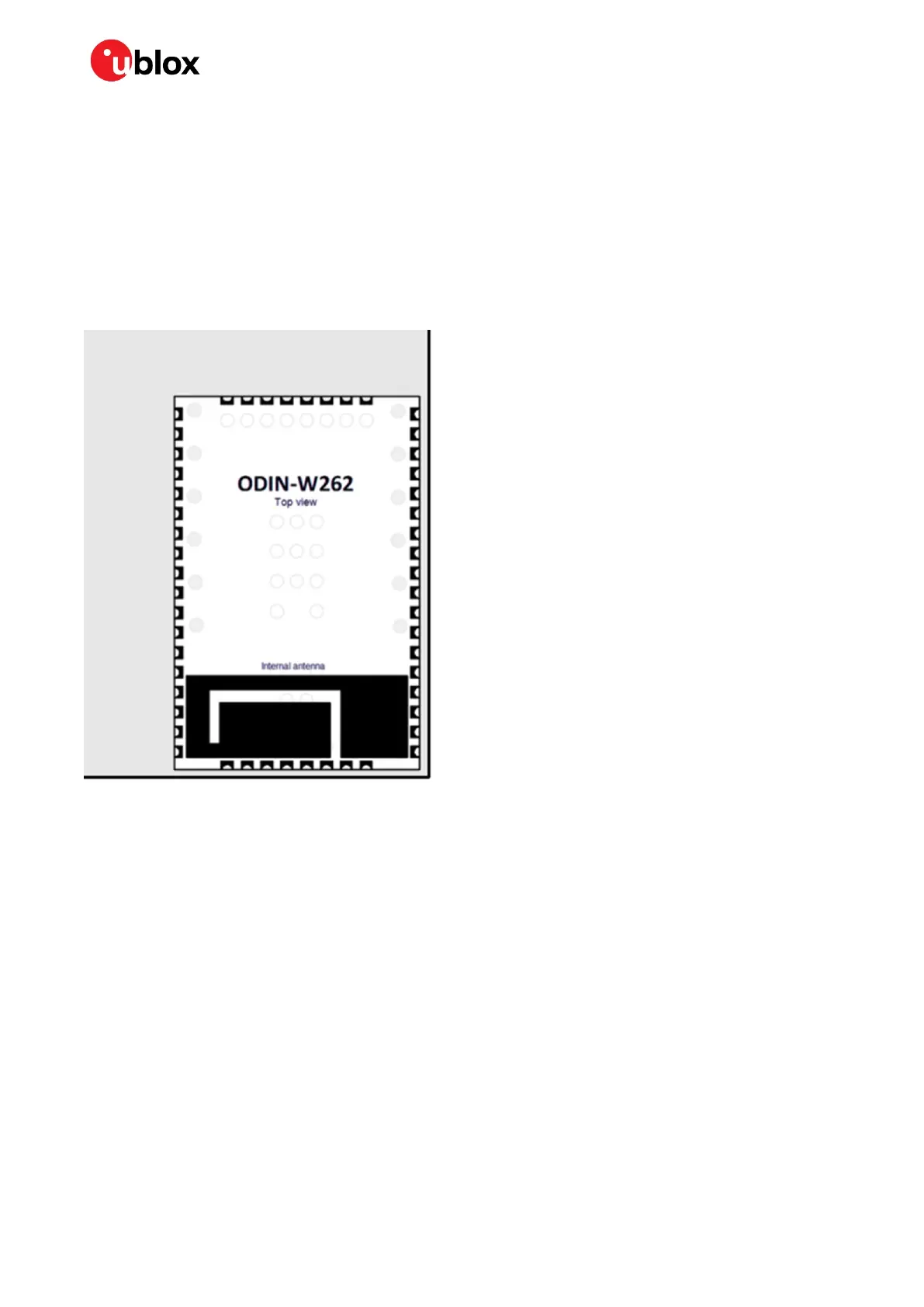
It is recommended to place the ODIN-W262/ODIN-W263 module so that the internal antenna is in the
corner of the host PCB (Pin B8 / C1 should be in the corner) as seen in Figure 8. The antenna side (short
side closest to the antenna), positioned along one side of the host PCB ground plane is the second
best option. It is beneficial to have a large ground plane on the host PCB and have a good grounding
on the ODIN-W2 module.
Figure 8: ODIN-W262/ODIN-W263 internal antenna.
3.3 Supply interfaces
3.3.1 Module supply design
Good connection of the module’s VCC pin with DC supply source is required for correct RF
performance. The guidelines are summarized below:
• VCC connection must be as wide and short as possible.
• Any series component with Equivalent Series Resistance (ESR) greater than few milliohms must
be avoided.
• The VCC connection must be routed through a PCB area separated from sensitive analog signals
and sensitive functional units. It is a good practice to interpose at least one layer of PCB ground
between VCC track and other signal routing.
There is no strict requirement of adding bypass capacitance to the supply net close to the module.
But depending on the layout of the supply net and other consumers on the same net, bypass
capacitors might still be beneficial. Though the GND pins are internally connected, connect all the
available pins to solid ground on the application board, as a good (low impedance) connection to an
external ground can minimize power loss and improve RF and thermal performance.
 Loading...


