UDP3305S Series Programmable DC Power Supply User Manual
Operation steps:
1. Connect the digital I/O interface on the rear panel to the external trigger source.
2. Press the power switch to power on the instrument.
3. Enter the trigger interface:
Press , select “Trigger”, and then press the “Enter” key or the knob to enter the trigger setting interface.
4. Select the trigger channel and set the parameters:
Press "Data line" to select D0, D1, D2 or D3.
Press "In/Out" to select trigger input or trigger output.
Trigger Input
Source under control: Press or to select one or more of CH1, CH2 and CH3 as the source under control.
Press the knob to confirm.
Trigger type: Press the "Left" or "Right" key and rotate the knob to select to trigger on the rising edge, falling edge,
high level or low level of the input signal.
Sensitivity: Users can set the sensitivity to high, middle or low.
Response mode: Users can set the output response type to "Output on", "Output off" or "Output toggle".
Trigger Output
Control source: Press or to select any of CH1, CH2 and CH3 as the control source. Press the knob to
confirm.
Trigger condition: Rotate the knob to select and set the trigger condition.
Polarity: Set the polarity of the trigger output signal to "Positive" or "Negative".
5. Enable:
Press Enable to enable the trigger function.
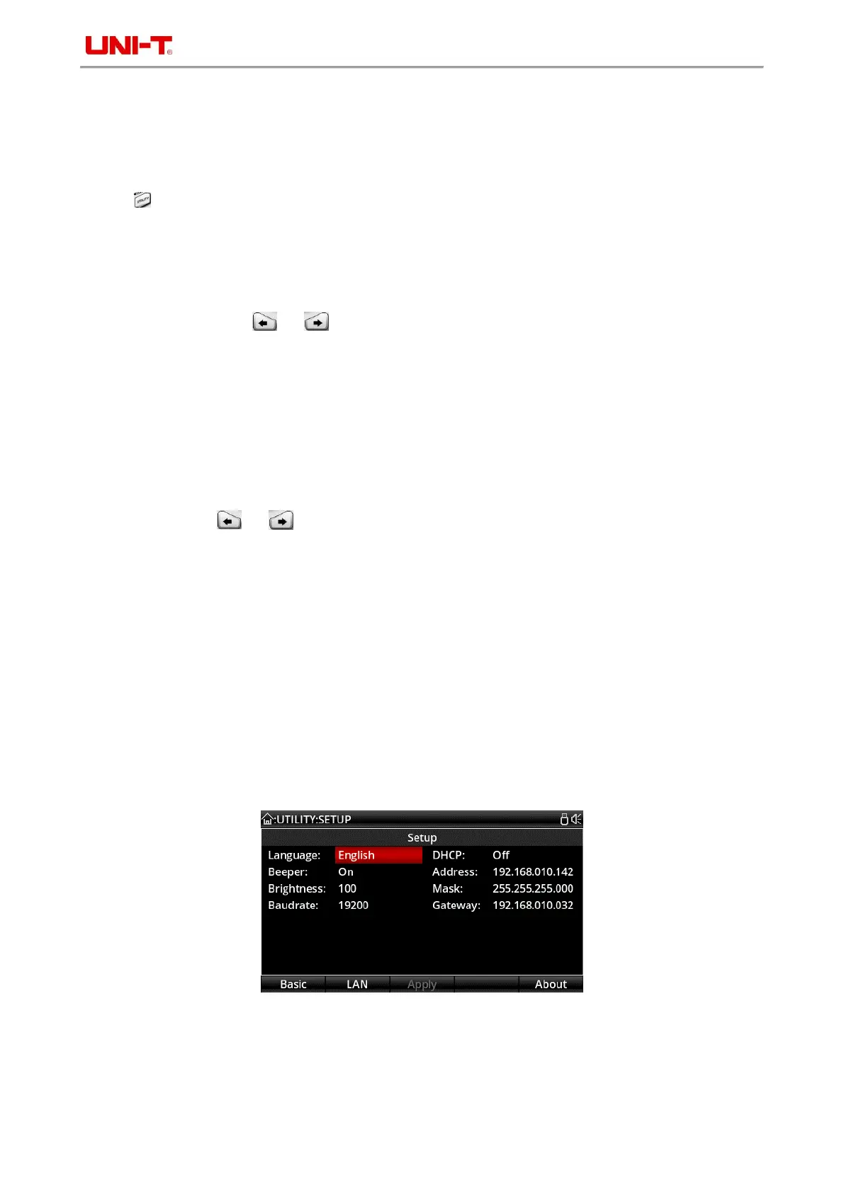
4.13 System Settings
In the system settings interface, users can view and modify system parameters, such as the IP address, baud rate
of RS232 interface, current system software version, and screen brightness.
System settings interface
 Loading...